What is the Connector Impedance?
I am looking at a SMA PCB Jack Receptacle by molex: Connector <--See Link
It says that the impedance of the connector is 50 Ohms. What exactly does this mean? If I was to short the chasis and the pin, would I measure 50 Ohms?
My application is a gate drive circuit that will be mounted on a PCB 90 degrees to my PCB with my transistor. My impedance between the gate driver and the transistor should be less then 10 Ohms. So, I want to make sure that if I use this connector, my effective resistance will not be 60 Ohms.
Thanks
Connectors are similar to very short transmission lines.That's why connectors have characterictic impedances and equivalent RLC components.
If you want to connect a source with 10 Ohm internal impedance to a load with different than this,you should-if frequency is sufficiently high-an impedance matching circuit.If the operating frequency is not too high,you can connect this source to the load through an impedance converter transformer or resistive matching circuit or directly..
All depends on frequency and permissible attenuation and return loss and delay.
If you connect a connector's live pin to ground,you'll see-theoritically-the same effect of a transmission line but practically you'll never see a short circuited transmission line characteristic because of connector's effective length.
Let me see if I understand you correctly. So you are saying the mechanical properties of the connector are such that it appears as a 50 Ohm load at high frequencies? Does the diameter of the inner dielectric play the biggest role in dictating the characteristic impedance?
More importantly, at 2 MHz, will the connector appear more like a short circuit, or more like a 50 Ohm resistor in between my two PCB's?
How about 10 Mhz?
Maybe it would be helpful if I provided a little more detail:
I am looking for a connector that is capable of conducting 10A for 100 ns every 500 ns. Am I even close with the connector I listed above?
The connector's impedance doesnt change with frequency ... just as a length of coax's impedance doesnt change
If either of them did, we would have to design a connector or coax for every freq there is (infinite!)
so for your examples 2 MHz and 10 MHz its still 50 Ohms ... at 100MHz, 1GHz, 10GHz etc etc
so yes its the mechanical properties of the connector or coax that determine its impedance
the diameter of the centre conductor, the circumference/ distance from the centre conductor of the outer conductor
The type of dielectric doesnt play so much on the impedance but it has a major effect on the loss of the cable (dB / metre at a given freq) general rule of thumb the more dense the dielectric the higher the loss... air dielectric being the best
As its impossible to suspend a centre conductor in an outer conductor cable "tube" the best that can be done is what Andrews did with some of their low loss big cables and that was to have just a spiral of teflon keeping the 2 conductors separated, achieving some 90-95% air dielectric
have a look here for an impedance calculator.... Coax Calculator - Microwave Encyclopedia - Microwaves101.com
Finally power handing .... cant comment on you specific example ... dunno if a SMA could handle those sort of RF currents even pulsed connector manufacturers would have that sort of data for their various connectors
Dave
VK2TDN
A 50 ohm transmission line (in this case a connector) doesn't present a 50 ohm impedance to whatever is connected to it - only when terminated with 50 ohms. So if you use the connector with a high impedance load it will look like a high impedance, not 50 ohms.
At your frequencies (10MHz) you can pretty much ignore the effect of the connector.
Keith
Hi, i suggest you this tool to calculate the impedance of a connector...
Tools & Converters
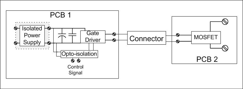
Forgive me...this is the first time I have dealt with frequencies this high. I do not feel that the problem has been defined well enough. So, this is the circuit I am trying to create:
Kieth, if I understand you correctly, the impedance presented by this connector will be minimal at 2 MHz? Ideally, what I am going for is a connection between the two boards that is zero Ohms. Using an SMA type connector at 2 MHz, is this achievable?
Is it wrong to assume that this connector would be better than an MTA type?
From my perspective, the wavelength of 2 MHz is around 150 meters. Even at 10 MHz, the wavelength is around 30 meters. So, it seems like I can ignore transmission line theory. Also, I thought the coaxial nature of the SMA connector would help to minimize the leakage inductance.
In case anyone was curious, I am evaluating multiple gate drive topologies with this particular MOSFET. So, I need a reliable way to interchange boards.
I appreciate everyone"s help and support!
Correct. The connector itself is never likely to be an issue below a few hundred MHz or a GHz or two. If you think of the "lumped" transmission line equivalent which is a series inductance and parallel capacitance, the figures for a connector are tiny - a few nH and a pF or two. These may matter at 1GHz but not at 2MHz.
The coax you use may have an effect. 50 ohm cable is around 100pF/m so that needs to be considered. However, if have have a large MOSFET then an extra 100pF may not matter.
Keith.
RF Impedance and DC Resistance are two very different things, as stated above. To prove this, just take a DC ohmeter and hook it across an audio speaker that you have lying around. Even though the speaker says it is "8 ohms", or somthing similar, the ohmeter will read something like 0.3 ohms!
The AC impedance is not the same as the DC resistance.
I understand, that are operating a gate driver with <10 ohm output impedance. If you connect it through a cable to the IGBT/MOSFET, the transmission line impedance actually will affect the gate waveform. At a cable length of < λ/10 related to the highest frequency involved in the driving waveform, it will mainly act as a series inductance, so it slightly increases the rise time. 50 ohms coax cable has about 250 nH/m inductance, you can calculate the cable effect for any length. Industrial gate drivers are mostly using twisted pairs to connect the gate, they have typically 90 to 120 ohm transmission line impedance, respectively a doubled specific inductance.
With very low driver impedances and high gate capacitances however, the cable can even cause some ringing. A 50 ohm SMA connector introduces only a few nH inductance and can be effectively ignored in this regard.
Correct, but this has nothing to do with the topic of transmission line impedance.
There will be no coax cable involved. The gate driver board is going to mount at 90 degrees to my half bridge topology. My plan is to use PCB mounted SMA connectors (one ninety and one straight), and attached the two with a barrel connector.
Digikey Part numbers: J474-ND, J496-ND, and J608-ND
The three components cost over S30 for one MOSFET, so I did not want to drop the money if they will absolutely not work. Unfortunately, I was not able to get a straight answer from Tyco or Molex.
Thanks for all of the feedback.
yes thats true .... if you were to use a 50 Ohm connector on 75 Ohm coax, yes of course you are going to get an impedance "bump" hence why you would use 75 Ohm connectors in that situation :)
The connector is just an extension of the transmission line, at whatever the impedance of that transmission line and connector are designed to be
Dave
I guess, the support engineers are expecting a basic level of RF engineering knowledge. But I think, the question has been clearly answered in the discussion.
- 1 cm of 50 ohm cable or connector length adds about 2.5 nH series inductance to your gate circuit
- regarding current rating, RF connectors are not regularly specified for DC currents, because the current capability at designed working frequencies is mainly restricted by skin effect losses. You should be able to estimate a low frequency current capacity from the specified contact resistances. Numbers like 5 A rms shouldn't be a problem.
Although you don't have a cable involved in your design, you still have PCB traces, that also form transmission lines respectively inductances. I would expect a much higher contribution from PCB traces to unwanted circuit inductance than the connector can ever make.
This experience has definitely pointed out how little I retained from my e-mag classes!
Thanks again, everybody, for the the input.
- Question about PC3.5mm and SMA connectors
- SMA to SMA connector
- How to use field replaceable SMA connector for best data.
- lines width versus the width of the component's connectors
- Is there any SMA Connector Model available ?
- HOW to chose coaxial cable and connector for prob feed patch antenna at 5.8ghz