Why do this match process as attached?
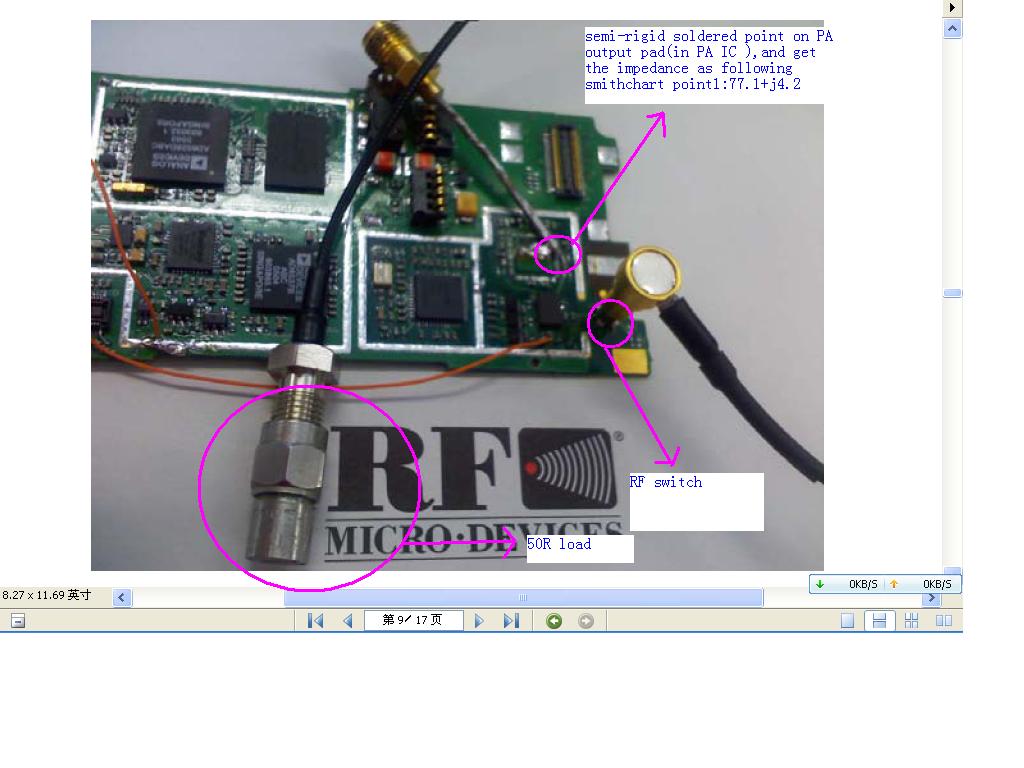
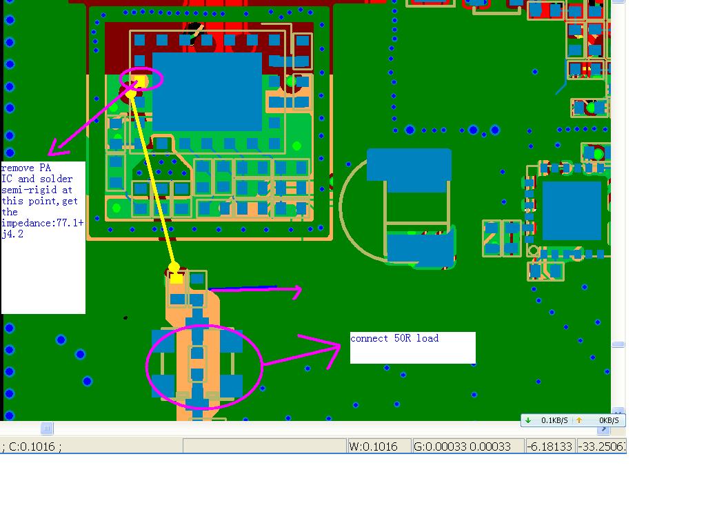
I am reading a paper about the match process of improving PA effeciency.(Vendor give the load pull impedance:44.52-j22.03)The paper introduces first measure the point 1 impedance:77.1+j4.2 (that remove PA IC , solder the semi-rigid at PA output pad,and remove the shunt components,connect series with 0 Ohm) ,then match to 44.52-j22.03.
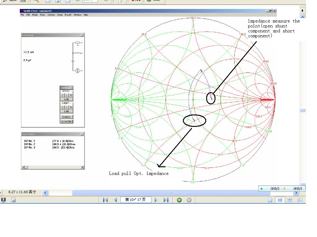
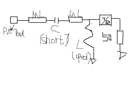
My question is what is the principle of above process.For 77.1+j4.2 should be the impedance as attached:
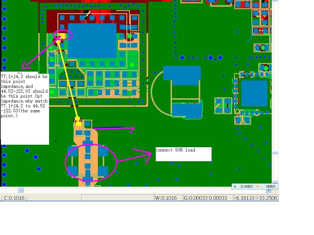
Why not direct match 50R load to 44.52-j22.03?
Thank you,
My two cents idea is: there is no possibility to set 44.52-j22.03 directly, because the semirigid cable is 50 ohms (when actually the PA output is not). You have to go first to 77.1+j4.2, and then match to 44.52-j22.03
I assume the PA doesn't have an internal output matching network.
Yes,PA does not have internal output match,datasheet supply load pull data.
I do not know why the above two matching ways are equivalent,and measure the same point to get two impedances(one is open the shunt short the series component;the other is load pull data) and then directly match each other,what is the theory?Normally,when we design match circuit,we do match step by step(series one and shunt other to get goal by smithchart,also the measured point changed with designator).It means that we can ignore microstrips,use the lump components to do match.As attached photo.
Can you give me a tip or documents about this equivalent match principle?
Anyone can help me?Thank you in advance.
Whether is it easy case?Anyone can tell me which book or article can find the answer?Thanks.