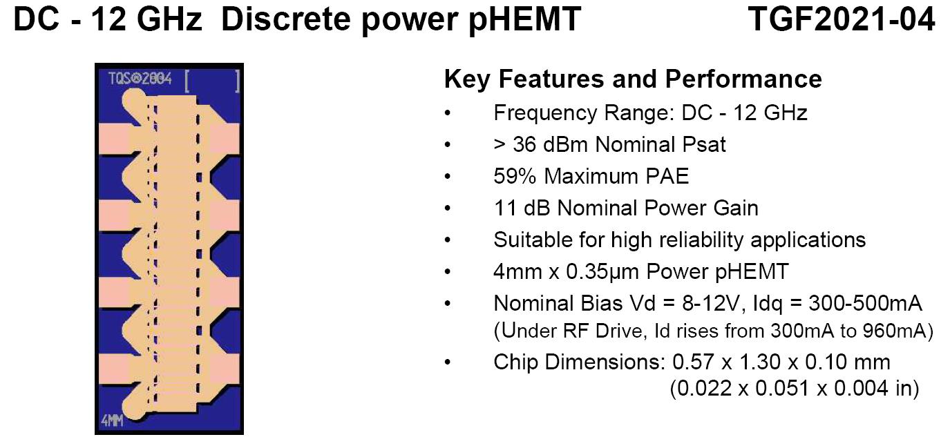
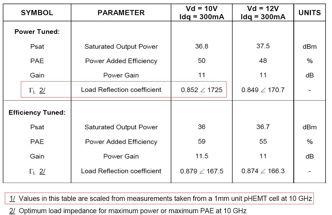
Load Reflection coefficient of Triquint TGF2021-04 FET
TGF2021-04 datasheet says the load reflection coefficient per 1mm unit pHEMT cell at 10 GHz is 0.852 ∠ 172.5≈4+j2,TGF2021-04 is a 4mm device(four cell ),So,What is the best load impedence when I connect the four cell together?
(4+j2)*4 or (4+j2)/4?
Mega Thanks
-cqcq
Neither.
How do you calculate "4+j*2" ?
Explain your calculation.
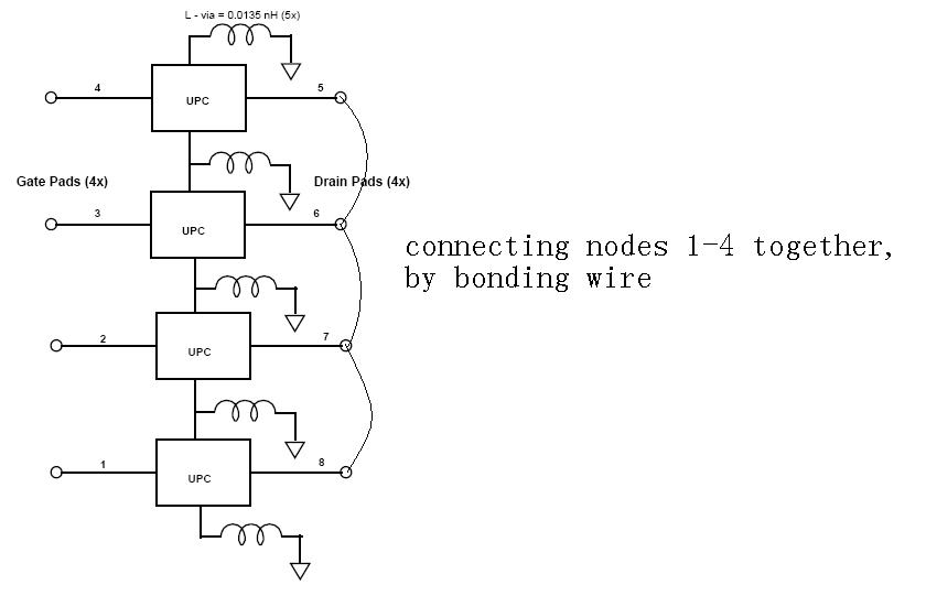
See attached figure.
Since there are spice model, I think it's better to simulate. And the simulate result should be better than specifications in datasheet.
Theoritical analysis won't work for this configuration because of loading effects of other devices onto one single device.
Connect 4 device in parallel and get include the realistic bonding wire models into simulation setup and make a Load Pull simulation and observe PAE and MaxPower contours on Smith Chart.
Because Optimum Load Impedance is critical and it should include all parasitic and interconnection effects of the configuration.
Simulation parameters which are provided are small signal model parameter and S-parameter.
And there are no small signal parameter for Vd=10V and Idq=300mA.
S-parameters are for Vd=12V and Idq=300mA.
First of all, this application is for power and a focus is power matching.
Here full nonlinear simulations are required for characterization.
So both small signal model and S-parameters are not useful.
Theoretical analysis can be useful a little since no nonlinear model for simulation is available in this case.
In actual design, you have to cut and try from initial value which I showed you.
coefficient Reflection Load 相关文章: