Input reflection coefficient
时间:04-04
整理:3721RD
点击:
Hello.
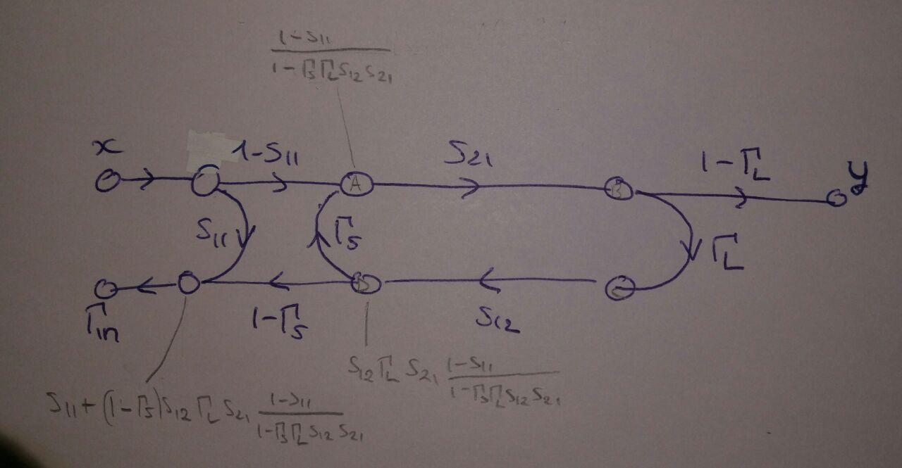
To get the reflection coefficient at the input (port 1) of a two ports device knowing its scattering matrix and the load at port 2 one can use the formula
I have the feeling my whole line of reasoning is flawed, I'd be grateful to anyone able to correct me!
Thank you in advance
If everything is fine and I use the right value for
To get the reflection coefficient at the input (port 1) of a two ports device knowing its scattering matrix and the load at port 2 one can use the formula
I have the feeling my whole line of reasoning is flawed, I'd be grateful to anyone able to correct me!
Thank you in advance
The key player is S12 here.If you make it zero, Gamma_in will be equal to S11.
All those equations come from "Mason's Flow" technique.
I already thought about that but never tried because I'm missing something here.
Here I made some hand calculations.
If everything is fine and I use the right value for
Gamma_S=0 in normal conditions.
Gamma_S=Source Reflection Coefficient
Turns out there were still a couple of problems on top of that that made the flowchart wrong:
1 - No need to add the (1-s11) branch: it is implicit in the definition of s21
2 - The node I marked C is actually a2 whereas B is b2, so a branch s22 connecting the two nodes is missing
Thank you very much!
Input reflection coefficient 相关文章:
- Different Input/Output matching
- How do you choose input power while doing loadpull?
- Why an input inductor required in all GPS LNA?
- Input and output impedance matching in Distributed amplifier
- In distributed amplifiers, is it total input capacitance of the gain stage or Cgs
- curve fitting for input and output matching