LNA Antennae Mis Matched
For my own interest and learning I have designed a LNA to operate at 450.325MHz. The LNA produces the desired NF and power when simulated but when placed on the PCB it produces a 20db Loss.
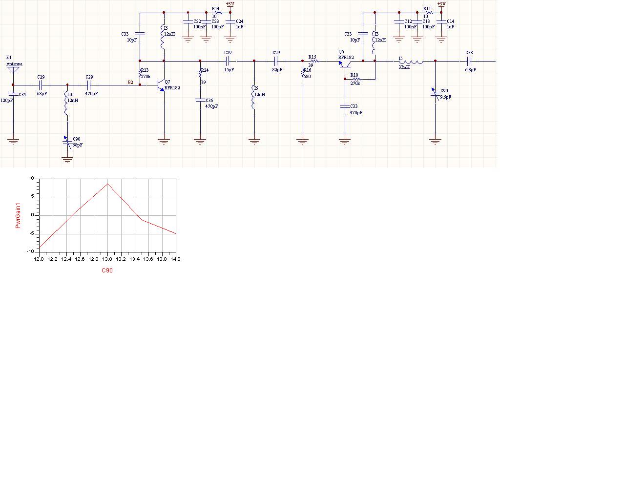
If you look at the figure you will see that C90 has a major impact on the gain.
The LNA is intended for a hand held pager. Part of the problem I believe is that if the antenae is moved around, its impedance will change as it comes close to foreign objects. This impedance change will effect my LNA NF and gain. I should mention that the antennae is a loop antennae and for now I am assuming it has an impedance of 50ohms.
My questions for those more experienced:
What is typically done in this situation? Do I need to isolate my LNA from changes in the impedance of the antennae and how do I do this?
I have spent alot of time unsuccessfully playing around with this match from the LNA to the Antennae. How should I solve this problem?
Can anyone recommend any decent text I should be reading?
Cheers
Need antenna info such as dimension, tuning components to be able to say something about that part but in general are loop antennas complicated to make working good without measurement equipment, especially if it is a small narrow band tuned loop. Start testing with a 1/4 wavelength monopole, a simple wire can be used.
Then you have a gain reference as a start to work with more complicated antennas.
Have not done any calculations but I doubt that it is 50 Ohm at antenna input as C34 is a very high value, almost a shortcut to ground.
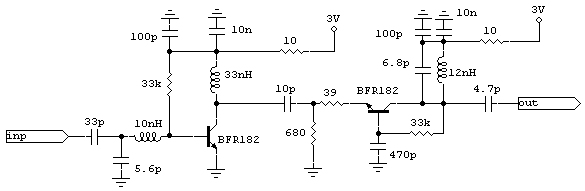
You have some big matching issues in your LNA design.
Try this one:
Did you measure the gain of the LNA alone, without the antenna (piece of coax cable from generator to C29-c34) ? Not the simulated one but that on PCB ? I think you should measure NF and gain of the LNA itself before to connect it to an antennna.
Even if 450 MHz is not a very high frequency, however layout and grounding could affect the performances: check them carefully.
Then you can also measure the return loss of the antenna by means of a network analyzer to be sure you have or not a strong mismatch.
Did you use in you simulation S-parameters for the inductors ? Low Q-factor could attenuate the signal, mainly in the resonant LC (i.e.: L10-C90 and L5-C33) so using ideal components you could mask the problem (that means simulation is OK, real circuit is KO).