Why RF tuning is so mysterious
I am set out on a project to destroy the myth that parasitics etc make theory and practice totally different for 2.4G tuning.
My problem is I have a diversity switch through which I look at one of the antenna a a time and make sure that the path looks like a 50 Ohm. I ensure this by looking at s11 in network analyzer.
Here is the problem I am having. When we look through a switch the transformation changes. So when I put a cap (Mostly o4o2 GRM series) in shunt on the source after the switch,instead of moving clockwise down the smith chart behaves in all different way according to fancy. When I asked experts, they say the caps at 2.4G has lead inductance and other parasitic that causes the problem and they have been tuning like this for ever. This is a lame excuse as the datasheet of the GRM components say below 10G the SRF a cap is still a cap and a very small lead inductance might be present.Same is the case with inductance.
Now I am proceeding this way. First I am planning to model the switch as a T network of L shunt C and L. So I open circuit the switch and measure S11. This will give me C. Then (1)I shot circuit the open end, (2) put a 50 ohm o4o2 (3) put a 100 ohm o4o2. From these 3 experiment I try to find the 2 Ls.
After getting a model like this and by using quick smith ..I try to observe each movement of smith chart with addition of one extra series or shunt L or C.
However to my surprise I have not been able to see Theory and Practice yet matching ?
Anythought.
First, you should observe (or try to) what your real circuit really is. I mean that you should know what is the equivalent network for each part of the circuit, including small lines, transitions from different line widths, connection to ground, real model of passives and so on. If you want, you can upload an image of your layout so we can have a look.
Usually the trick for this simple design is only the one I have mentioned.
The most accurate thing you can do is to get (by measurement or from datasheet) Sparameters of each sub-circuit (the resistors, the switch, lines and so on) and cascade them in a simulator, then compare the result with end-to-end circuit.
Tools like quicksmith are useful, but only for a first approach, as they don't have the flexibility of a real simulator.
I hope it can help.
Mazz
I don't know what cap values you use in your circuit but for example 8.2pF 0402 GRM1555C1H8R2DZ01 has SRF at 2.5GHz.
Definitely you have to put in your design the S-parameters of each component used (or of most of them, for minimum tuning).
What about the inductance in the ground path of your shunt elements?
The mysterious nature of RF tuning is pretty much the only thing keeping us all employed! I like it just the way it is.
At some point the entire RF developing it resume to tune a circuit.
But this mysterious nature of RF tuning is what makes the beauty of the Radio Frequency, even sometimes is like listen Johann Strauss and Led Zeppelin in the same time.
Ok So,
I got the S parameter of the capacitor from Murata datasheet at 2.4G. Now I am trying to get the s parameter of the diversity switch TQS5200
To get S parameter of the Antenna I took a measurement close to the Antenna and noted the s11. This might give me the impedence of the Antenna.
To match the theory and practice I am now trying to substitute each of them by their blackbox and check if I can get the desired result.
Is there any free simulator you folks know where I can simulate the whole set up.
If not is there a way to map the S parameter to Components to LC PI network. Then I can use Quick smith to simulate it.
PS: The return path I assume is the gnd plane.There is a short transmission line.However I do not see it will have much impact.
The
---------- Post added at 02:10 ---------- Previous post was at 02:08 ----------
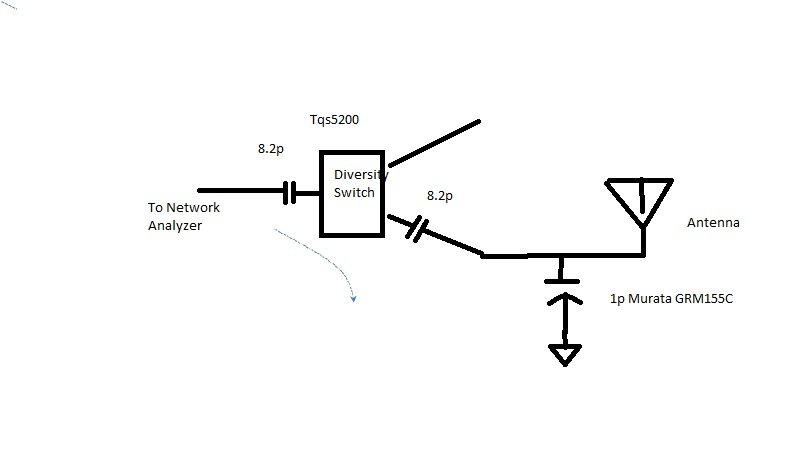
The pic is given here for the set up.