Transmission Line Matching Issue: How to derive formula
时间:04-07
整理:3721RD
点击:
Hi, there
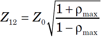
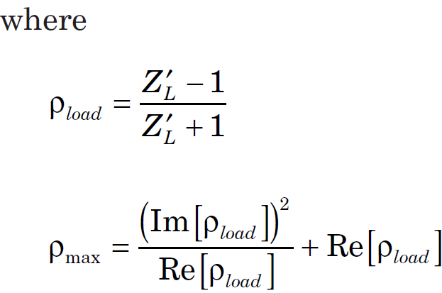
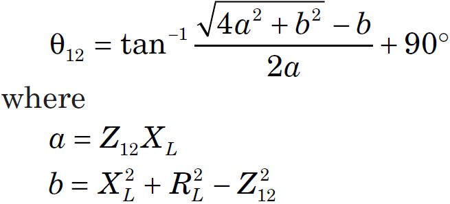
I am now reading a paper named "The Yin-Yang of Matching: Part 2?Practical Matching Techniques" by Randy Rhea, In the second section, the paper presents formula for general transmission line transformer, and I quoted here
I can not find the way to derive these two formula, can anybody give me a clue?
also I upload the original paper, if any of you guys may need.
Thanks
Julian
Now at the end of the Z12 segment we can write:
Since at the segment of the tx line with characteristic impedance, it should match the load to Z0.
Now if you try to solve tan(theta) from here, you should get to your answer.
This is the way I understood after glossing through the paper for 3 minutes. So I may be wrong and if you don't feel this is not going anywhere you might as well pursue another line of thinking.
I am now reading a paper named "The Yin-Yang of Matching: Part 2?Practical Matching Techniques" by Randy Rhea, In the second section, the paper presents formula for general transmission line transformer, and I quoted here
also I upload the original paper, if any of you guys may need.
Thanks
Julian
I quickly read through the paper and I believe the derivation may have been along the following lines:
First the new circuit would look like:
Code:
    ------------------==========================
    |                                           |
    |                                           |
[Source]      Z0               Z12             [ZL]
    |                                           |
    |                                           |
    ------------------===========================
Code:
Z0 = Z12(ZL - j.Z12.tan(theta))
            ---------------------
            (Z12 - j.ZL.tan(theta))
Now if you try to solve tan(theta) from here, you should get to your answer.
This is the way I understood after glossing through the paper for 3 minutes. So I may be wrong and if you don't feel this is not going anywhere you might as well pursue another line of thinking.
Hi: cobolcjava
I know the well-known formula to get transformed impedance and in fact I can derive these two formula, what I really get confused and want to know is the physical significance of the quantity ρ_{max} , it shows itself in such a unnatural way, and I can not explain it at all? Can u give me any advice? Thanks