Inductor with differential port in ADS
I have encountered a problem for simulating a very simple lumped inductor in ADS schematic.
The picture of schematic is attached.
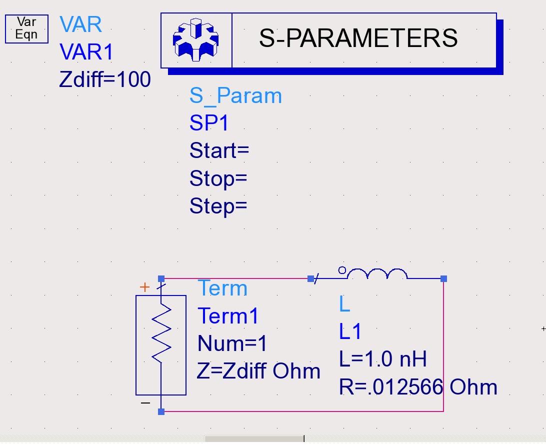
I am simulating this at 100 MHz, therefore with L=1nH, Q should be 50.
Using two single ports at the terminals of inductor is easy and gives the correct results. However when I am assigning differential port to the inductor S11 is something like -0.02dB.
It should be possible to get the correct result with differential port. I set the Zdiff of the port to 100 ohm and it didn"t work either.
What am I doing wrong in my simulation?
waiting for your kind help
I don't know how your current setup can work, but here and here how you can use the ADS momentum to define each port type
The correct value would be - 0.002dB
What value do you expect?
Dear jackreloaded,
Thanks for reply. The links that you put in your post are for Momentum and actually I set up this simple schematic because I had this differential port problem in Momentum. Then I tried to understand that which part of my setting is wrong.
I drew an inductor and assigned a differential port to it in the same way as explained in the Momentum help document.
then I obtained s1p (one-port S parameters) for my inductor. S11 (dB) from Momentum results is -0.3dB! (I suppose that this should not be the S11 of my inductor)
Is this -0.3dB for differential port normal?
What pint am I missing in here?
---------- Post added at 13:36 ---------- Previous post was at 13:33 ----------
Thanks for reply,
Why the correct value is this?
Most probably I am confusing the single mode S parameters with mixed-mode ones.
Could you explain in detail that why S11 is not like -40dB?
By the way, Zdiff=100 ohm here is correct, right?
I see where your misunderstanding is.
For the two port case, your impedance into the circuit is 1nH + 0.012 Ohm + port impedance on the other side.
For the one port case, your impedance into the circuit is 1nH + 0.012 Ohm.
So for the one port case, you see approximately a short circuit and get S11 ~ 0dB. This is the correct result for a one port simulation, if the inductor has small value and small series resistance.
Dear volker_muehlhaus
Really thanks for your detailed explanation.
Now everything is clear.
Just one question: is Zdiff=100 ohm correct?
The value is only relevant if you want to look at these S-parameters in the data display.
If you use the inductor results in the circuit, or calculate the L/Q values from the simulation results, the port impedance does not matter. You can use 50 ohm or 100 ohm, it makes no difference.
volker_muehlhaus
Dude thank you for explanation.
Regards,
Hamid
differential Inductor ADS 相关文章:
- Loadpull for Differential PA
- How come differential cascode structures affect on PA characteristics?
- Microstrip differential impedance depending on line width
- Differential Input For Dickson Chgarge pump Rectifier
- Multiband Differential Rectifying Circuit (re symmetry or not)
- Differentially-Fed Rectifier