Loadpull for Differential PA
https://www.edaboard.com/showthread....ht=ideal+balun
https://www.edaboard.com/showthread....ht=ideal+balun
https://www.edaboard.com/showthread....ht=ideal+balun
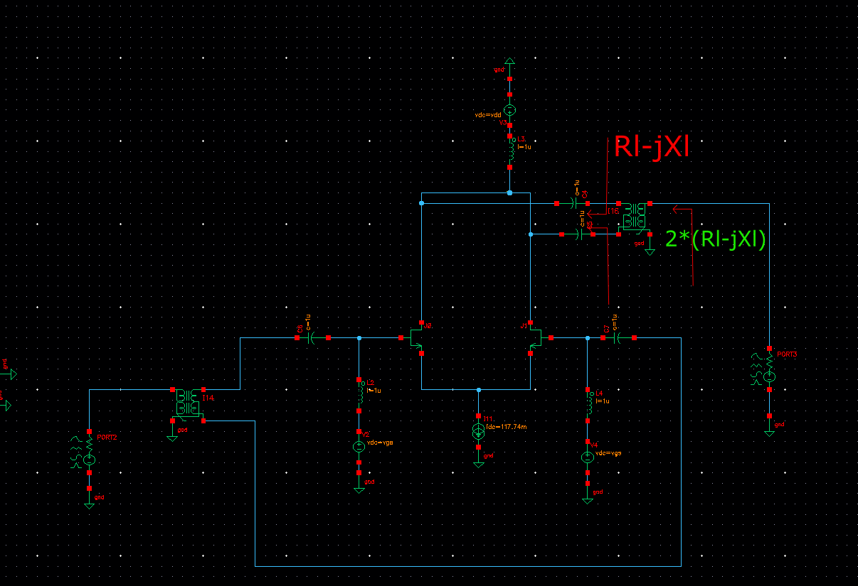
First of all I would like to know whether the set up is correct in the figure.
Here is my concern. If I have single ended configuration, I will have Zopt from loadpull as, say, Ropt+j*Xopt. And the impedance looking into the output of this single ended is ,let, Rl-j*Xl.
Now, I have a Differential configuration. I connected the outputs of the two single-ended configurations to ideal_balun. So the impedance looking into the ideal_balun is 2*( Rl-j*Xl) (in this case, output side)
should the value I get from the loadpull, ideally, be 2*(Ropt+j*Xopt)?
Simply your thoughts are all wrong.
Differential mode can not exist in your circuit.
Surely learn basic linear circuits theory before EDA Tool Play.
-Ideal Balun does not do Impedance Transformation.It acts simply as Diff-to-Single Ended so the Impedances ( Input/Output) are same..
-This structure has high Output Impedance ( I don't know the details but looks like it) so it's not convenient for PA.A PA should have more or less an Output Impedance closer to Load to match easily..( I presume the PA will work @+20dBm or more )
1. Your circuit is flawed and must be corrected, you have shorted the output.
2. Not sure if the corrected circuit is exactly equivalent to "two single-ended configurations". If it is, your calculation would be correct.
3. I don't see an advantage of using a balun in simulation. Why not simply use a differential load?
For load value control in Cadence Spectre, we have to use balun for differential load.
I inferred that you are doing mmwave from your previous posts. If that is the case, that current source will eat away unnecessary voltage headroom. I read somewhere that people don't use the current source beyond 5GHz (I have forgotten the paper). Just ground your sources. You will get a pseudo-differential pair but larger voltage headroom.
And as someone already pointed out, your outputs are shorted. Also use 'dcblock' and 'dcfeed' else you will can run into convergence issues while doing HB-PSS (atleast I did in 45nm).
But you don't even need all of that. Connect your DC sources directly to the center tap of the transformers. True for both input and output.
What you get from the loadpull is the impedance that the output port wants needs to have. Its is as simple as that.
How are you saying that output is shorted, is it because the C terminal of Ideal_balun connected to ground?. Also, I already connected 'dcblock' and 'dcfeed', where else should they be connected?
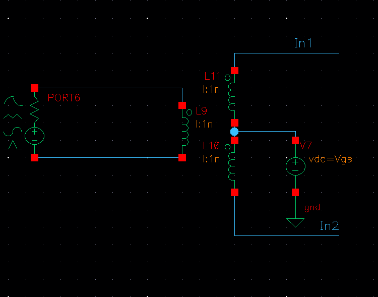
I don't think there is center tap transforment in analogLib. Should I make something like this?
Can you understand differential circuit ?
https://www.edaboard.com/showthread.php?386764#2
No. There is no coupling between L.
Can you understand actual transformer ?
Ideal transformer is not mutual L.
Surely learn very basic things before EDA Tool Play.
A wire between the differential output nodes is usually understood as short. Review the post #1 schematic.
Look at the symbol of a balun very carefully and you will see what we mean.