Frequency Multipier in ADS
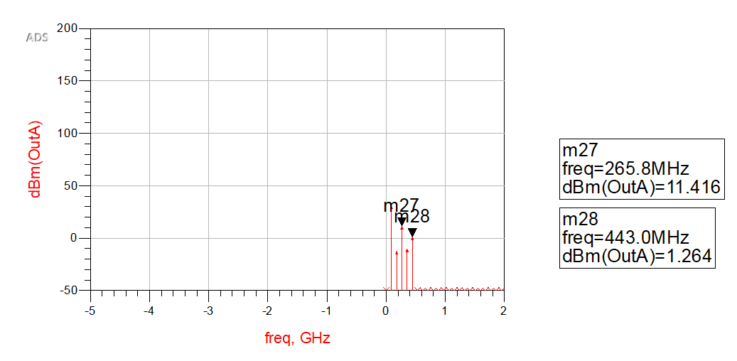
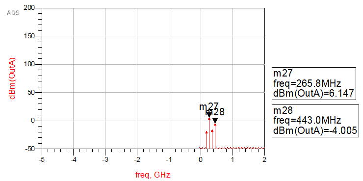
I have designed and simulated a frequency multiplier in ADS but my result is not acceptable. My Frequency multiplier conversion loss is shown below.
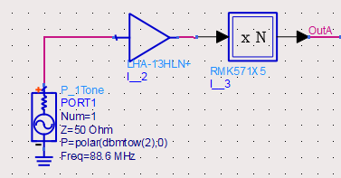
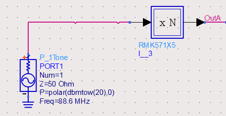
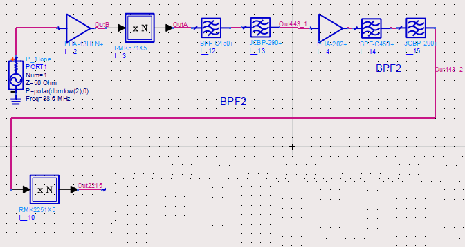
Here is my circuit.
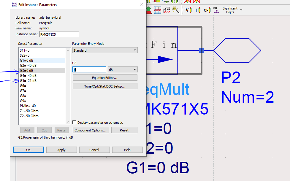
Here is my settings.
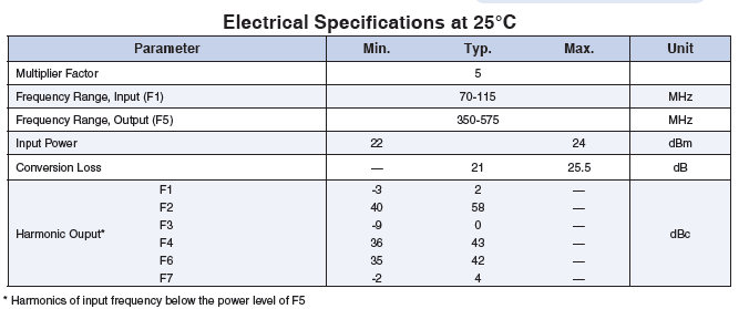
why the third and fifth harmonics of Frequency multiplier aren't the same? Because and regarding the datasheet, The third and fifth harmonics have the same power gain( I have set 0db for third harmonic which has the same power gain related to fifth harmonic)
Did I make a mistake?
Based on ADS tutorial:
https://edadocs.software.keysight.co...pageId=6083662
Both components are 50-ohm matched, maybe models have some parameters like supply voltage?
I would try to put DC-blocks around LHA-13HLN
Your parameter settings don't comply with the datasheet. Notice that harmonic levels are relative to 5th harmonic output. If G5 is -21dB, G3 should have a similar value.
I really appreciate your help
I created a Data items and add LHA-13HLN s-parameters touch stone so it doesn't have any supply voltage. However, I check the circuit by removing the amplifier
but I get the same result.
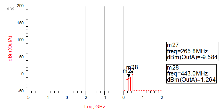
Thank you. I assumed as well, but based on Keysight tutorial "G3 Power gain of third harmonic relative to input tone" so the datasheet and G3 parameters are the same. However, I simulated your suggestion but I got this:
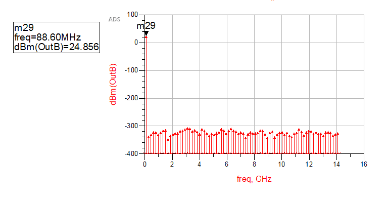
I just simulated my amplifier and I got this result. By injecting 2dbm I got 24dbm amplified signal.
Not the same, datasheet value is relative to output level.
Neither in post #1 nor post #4, 3rd and 5th harmonic have similar level. About 10 dB difference, but with opposite direction. So there's obviously an additional effect in the model behavior.
Sure you have set HB analysis parameters appropriately?
Yes , you are right. I made a mistake not to take into account the "Input" and "Output" words.
I changed and made my circuit bigger. Here is my present circuit (double mixer) (5X , 5X) I set my input frequency order in harmonic balance simulation about 150.
As you can see in the first diagram everything is good but in the second stage strange frequency appeared.
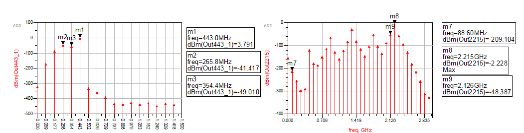
For example where did 2.126Ghz frequency come from?
Thanks
Unwanted output signal is mixing product of 4th harmonic (354 MHz) which isn't significantly attenuated by the bandpass filter.
Thank you, how did the 4th harmonic of (354Mhz) generate with that high amplitude? the frequency multiplier mentioned it has low harmonics and IM components.