Design of Three coupled tune circuit as bandpass.
时间:04-06
整理:3721RD
点击:
Dear all, Please i need help designing a three coupled tune circuit as a bandpass filter. Firstly i'm a novice in microwave, so please bear with me. Please is there a formula that can be use to design these things? I'm quite frantic so i don't really want to go into so much depth, as I've been told it's quite hard to design from scratch.
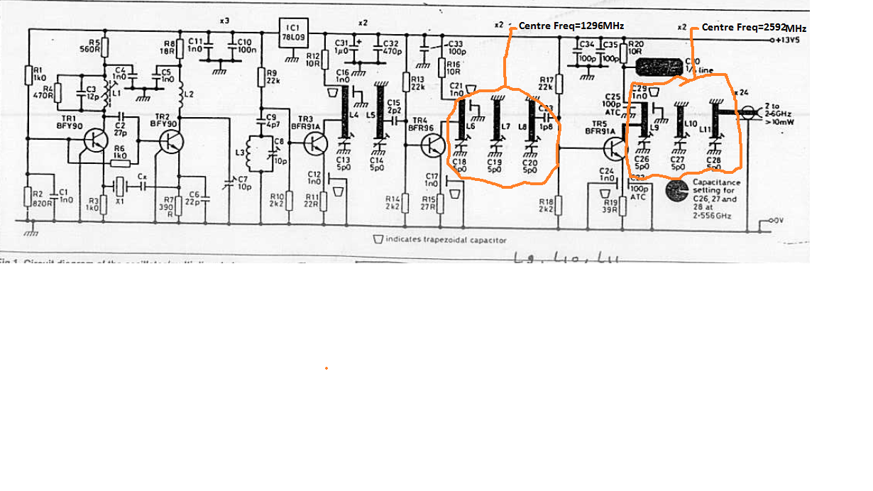
I'm using a FR4 board with a dielectric of 2.4, height of the board= 1.5mm, impedance of 50 Ohms. The schematic can be seen below in the attachment.
In addition, how can i find the inductance per unit length and Capacitance per unit length of each micro strip line in the diagram. P.s i've read quite a few text books and they seem too complex/confusing for me. Any suggested values will be appreciated.
Thanks for your time.
Search the net for the freeware Ansoft Designer SV (Student Version).
This will do simple microstrip filter simulations as you need.
- design and simulation of cross-coupled VCO using keysight ADS
- [moved] Fully Cross-Coupled Rectifier Configuration in Terms of Transistor Terminals
- Microstrip coupled lines
- Infineon BGT24MTR11 mmic: should RF in/outs be decoupled from ground?
- Coupled line filter design
- Unwanted DC voltage induced on a varactor coupled to DR? (dielectric resonator 10GHz)