What's the reason of this result(E_field distribution) in these antennas?
时间:04-06
整理:3721RD
点击:
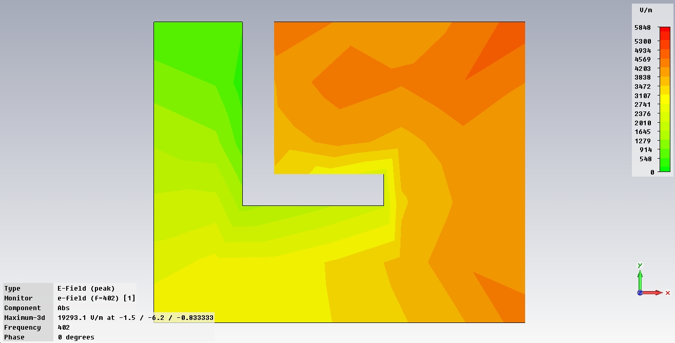
There are two different antennas shown in the following pictures. The first one has a patch with uniform width and the second one has a patch with non-uniform width.
So the question here is :
Why is the E-field distribution in the second antenna smaller and more uniform than the first antenna?
How can we explain, why is the E-field distribution in the second antenna smaller and more uniform than the first one?
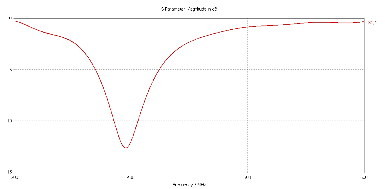
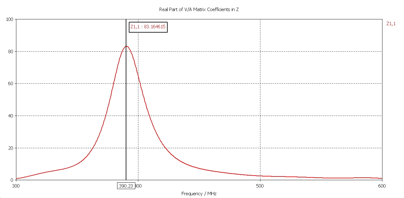
The first antenna:
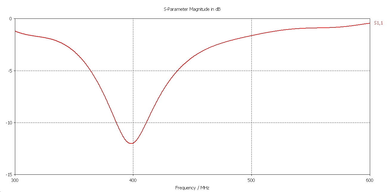
The second one:
So the question here is :
Why is the E-field distribution in the second antenna smaller and more uniform than the first antenna?
Code:
Is this true? "I think  that the we can interpret this result by this equation:
E=-Gradient(V)
Can we use this equation in this manner :
  E=-Gradient(V)=-Gradient (Z*I)=-(Z*Gradient(I)+I*Gradient(Z))
  But ,what's the continue?"
The first antenna:

The second one:
- How to use field replaceable SMA connector for best data.
- How to calculate E_far field in CST with probe
- How to compute the electric field inside a dielectric volume?!
- Is this possible? (EM field, sensor device, writing to NFC tag, interface device)
- How to combine E theta and E phi to get E field
- reactive fields and radiating fields