vco generates odd harmonics high
I am experiencing the vco MAX2620 and work very well but generate odd harmonics high (experiment in VHF).
This sounds like the harmonic content of a nearly square wave: "odd harmonics high(er amplitude) and the even harmonics are lower (amplitude)"?
So, you do not have a pure sine (sinusoidal waveform) wave being produced.
Can you be specific on the relative amplitudes of the even and odd harmonics?
Jim
---------- Post added at 07:41 ---------- Previous post was at 07:29 ----------
Also note, in the datasheet on page 6 under Typical Operating Conditions the spectral photo showing lower even harmonics and higher odd harmonic output:
http://datasheets.maxim-ic.com/en/ds/MAX2620.pdf
Jim
VCO may be differential, that's why even harmonics are lower than odds..
Here you can find the harmonic amplitude terms for various waveforms, or pulse duty-cycles.
http://www.wenzel.com/pdffiles1/pdfs/choose.pdf
But MAX2620 has differential outputs that can be used together or independently.
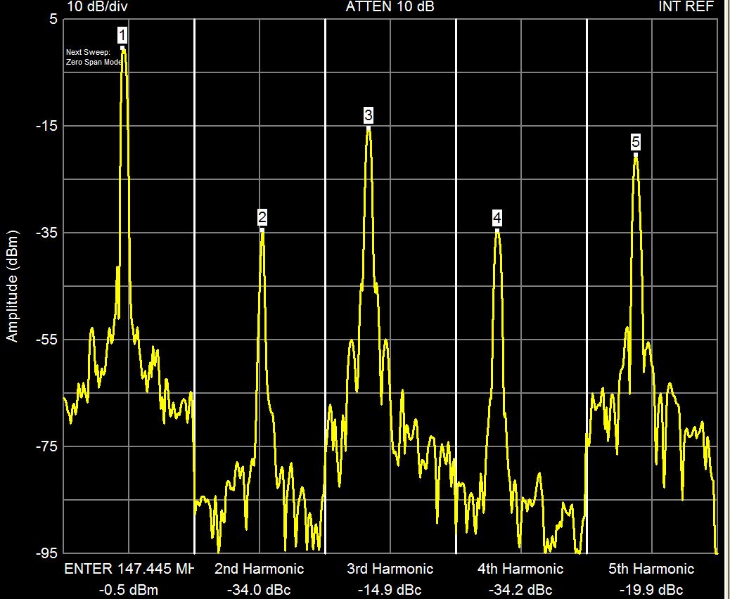
Hi guy , I have mesure the armonic and the result are:
144.4Mhz -0.4dbm
2° harmonic 288.8Mhz -34.8 dbm
3° harmonic 433.2Mhz -15 dbm
4° harmonic 577.6Mhz -36dbm
5° harmonic 722Mhz -20dbm
-My question is , when use this oscillator for utilize like local oscillator, (with ne602 o another mixer) the odd harmonic are a problem?
-The IC cost 8S ! and Not has a sinusoidal wave !!
-When I test the IC I burn 3 chip of MAX2620! this chips are very delicate! (I may have discovered the reason why we burn, I sold this chip with flux "fry powerflow flux", I suspect that the pin lead with this paste although it is a high resistance, when apply the paste sold and NOT clean! , I change the flux and not burn chip!)
It appears the primary purpose of the two outputs is to drive a mixer separate from a prescaler (or PLL) chip with a good degree of isolation provided between the two outputs.
Also notice in the data sheet the power output differences between Out and /Out (about 10 dB, the difference between -2 dBm and -12.5 dBm respectively) for both ports terminated in 50 Ohms per "TYPICAL OPERATING CIRCUIT PERFORMANCE" charts on page 3.
Jim
---------- Post added at 11:49 ---------- Previous post was at 11:43 ----------
If your concern is the 2nd and/or 3rd harmonics going to the mixer, recommend inclusion of a low pass filter between those two stages; there is likely good anyway that impedances need to be matched and/or the output power for a diode ring mixer would have to be bumped up to +7 dBm with an amplifier anyway ...
So, how do your measurements compare to the spectrum chart shown on page 6 (Title: OUTPUT SPECTRUM FUNDAMENTAL NORMALIZED TO 0dB) of the datasheet (even though that figure is for 900 MHz operation)?
Jim
For measure the armonic I use a spectrum analyzer "Signal Hound", send the image of screen and send the demo board of MAX2620

Very nice work.
Everything seems to be working according to how it should work; harmonic content looks normal coming more or less straight from a VCO/Oscillator stage with not LP or BP filtering (things in real RF world are never 'clean' unless you provide adequate filtering or filters).
For input to a mixer for use over a limited freq range, you can probably fore-go a low pass filter if your amplitude is sufficient to drive the mixer.
Goof luck and let us know how it turns out.
Jim