Reference for VCO and PLL
Im working with a system that requires a 23.8 - 26.8 GHz VCO (HMC739LP4). During lab testing, to maintain stability I setup a phased locked loop using the divide by 16 output on the VCO, a HP frequency synthesizer as the reference, and a mini-circuits double balanced mixer as the phase detector.
This setup works great, but when I move towards the final product design, I will have to create my own stable reference ~1.45 - 1.6 GHz and move away from using a bench-top synthesizer. What are some of the common methods to create such a stable "tune-able" reference? Is this something a DDS or good DAC can accomplish? Or would it have to be more hardware based (like a crystal) to maintain true stability?
Thanks in advance,
Sami
Somewhere, someone has to provide a "golden" frequency
standard. At test you would use the test equipment set's
master 10MHz most likely, as everything else is slaved to
that. Though maybe there's higher frequency references
made available in >20GHz test gear, I wouldn't know about
that.
PLL chips that can take 10MHz to 1-2GHz are plentiful. You
might end up with a double up-conversion, 10MHz to 1.5GHz
by first XO, VCO, PLL and then 1.5GHz to 30GHz/N by a
second VCO, PLL. Seems like you have a handle on the 30GHz
prescaler. Not sure what's out there for PLLs that can take
>1GHz fRef. You might have to use a lower fRef or divide the
1.5GHz to a lower fRef while using it for your measurement
reference as well?
In order to create a stable and clean reference another PLL can be used.Because Reference Signal for PLLs is very important and they have to be produced with Ultra low Noise and Ultra Stable specifications.
I would design another PLL ( Analog Devices ) with a High Quality VCO ( Synergy Microwaves or equivalent) to get my Reference Signal.Some AD PLLs have their own VCO's..think about them too
A handy source comes from short wave stations which broadcast time beeps every second.
https://www.nist.gov/pml/time-and-fr...o-stations/wwv
Thanks all!
Very helpful. Couple of follow up questions if you don't mind.
In digikey they lumped "clock generators" with frequency synthesizers. Is there a difference for this purpose? For example, I need a 1.5MHz and 1.5 GHz reference. For 1.5 MHz there are chips for less than a dollar that input a crystal, have programmable outputs, have an incorporated PLL (Datasheet) are is specifically called a clock generator.
For the 1.5 GHz reference, there are a few chips out there which reference a crystal, internal PLL, ...etc.. but call themselves frequency synthesizers datasheet.
After looking at the data sheets, I dont see any real difference in terms of using either chip as stables references for much higher frequency VCOs. However, better to ask than to find out the hard way.
Thanks again for all the time and help,
Sami
This one is much more better for your 1.5GHz Reference.
https://www.analog.com/en/products/adf4360-4.html
Thank you so much! That chip is a much better option for what I need.
Another question if you dont mind, its more of a general question about PLLs. For my lab testing I am created a kind of PLL.
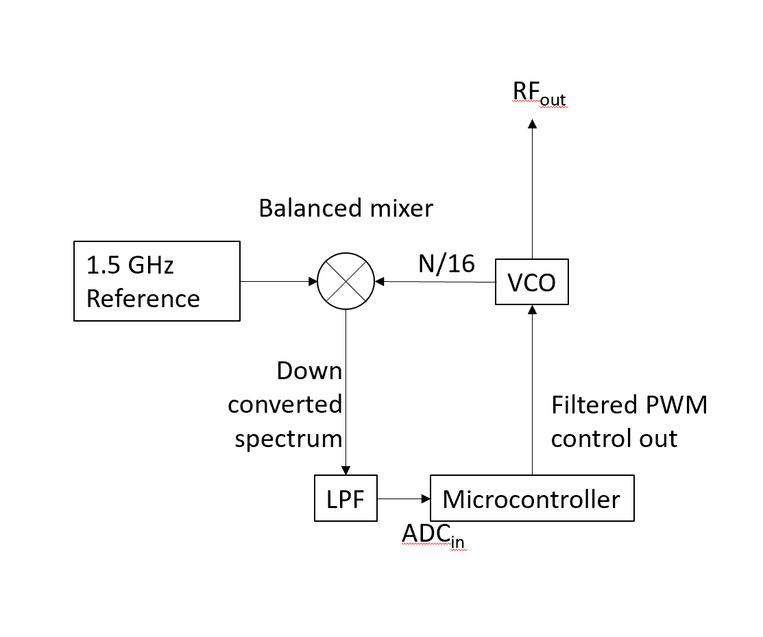
I am using a HP frequency synthesizer to create my 1.5 GHz reference, a balanced mixer as my phase detector, and a 10KHz low pass filter as the loop filter. The microcontroller samples the PLL output and adjusts the VCO accordingly.
Since I am using a balanced mixer as my phase detector, the filtered down converted spectrum contains the difference frequency between the ref and VCO output, usually a signal in the mHz to 10Hz range. That makes sense to me, and its how i maintain stability, by keeping that frequency as close to zero as possible.
How do these chip sets perform their internal PLL? Do they too use a microcontroller or digital circuitry like the example above? Or is there a much more elegant analog solution to maintaining loop stability?
Bonus question:

If I am using a mixer topology like above, will I ever see a DC offset on the output? If my loop filter has a low enough cut off to attenuate (ref - VCO) I can't get my loop to work. But if i set the filter high enough to keep that mHz - 10 Hz signal, i can get my loop to stabilize. I will freely admit, user error here is very likely.
Thanks in advance,
Sami
you are not asking the right question. anyone can slap a junk signal source onto your board, and it will lock up. But what PHASE NOISE at the 23 GHz output does your system require? Because whatever clock phase noise you input at 1.5 GHz, will get multiplied to become at least by 20 LOG 16 worse at 23 GHz.
That's part of what we aim to figure out during bench top testing. Thankfully we aren't doing anything too fancy: Exciting two CW tones, 24 and 24.25 GHz and looking for the intermodulation product 24.05 GHz. Most of these clock generating chips boast phase noises <-100 dBc 1Mhz away from the carrier, so it seems having my two tones 25 MHz apart shouldn't cause too much of an issue? Then again, I'm fairly new to frequency generation, up till now I've gotten to rely on nice test measurement equipment.
Thanks,
Sami