Tuning range of an LC VCO
I asked how can i display the output frequency of an LC VCO versus control Voltage of its varactor. If you have a tutorial which can help me.
I'm so grateful to help me.
Sincerly
Do a HB analysis with a sweeping variable ( Vtune ) then plot freq. vs. Vtune.
You can do it in ADS or Cadence SpectreRF..
Thank you, i use ADS in simulation, however i need a clear tutorial which specify all parameter and equation. I'm so grateful to send me tutorial in ADS how to display tuning rang of a differential LC VCO .
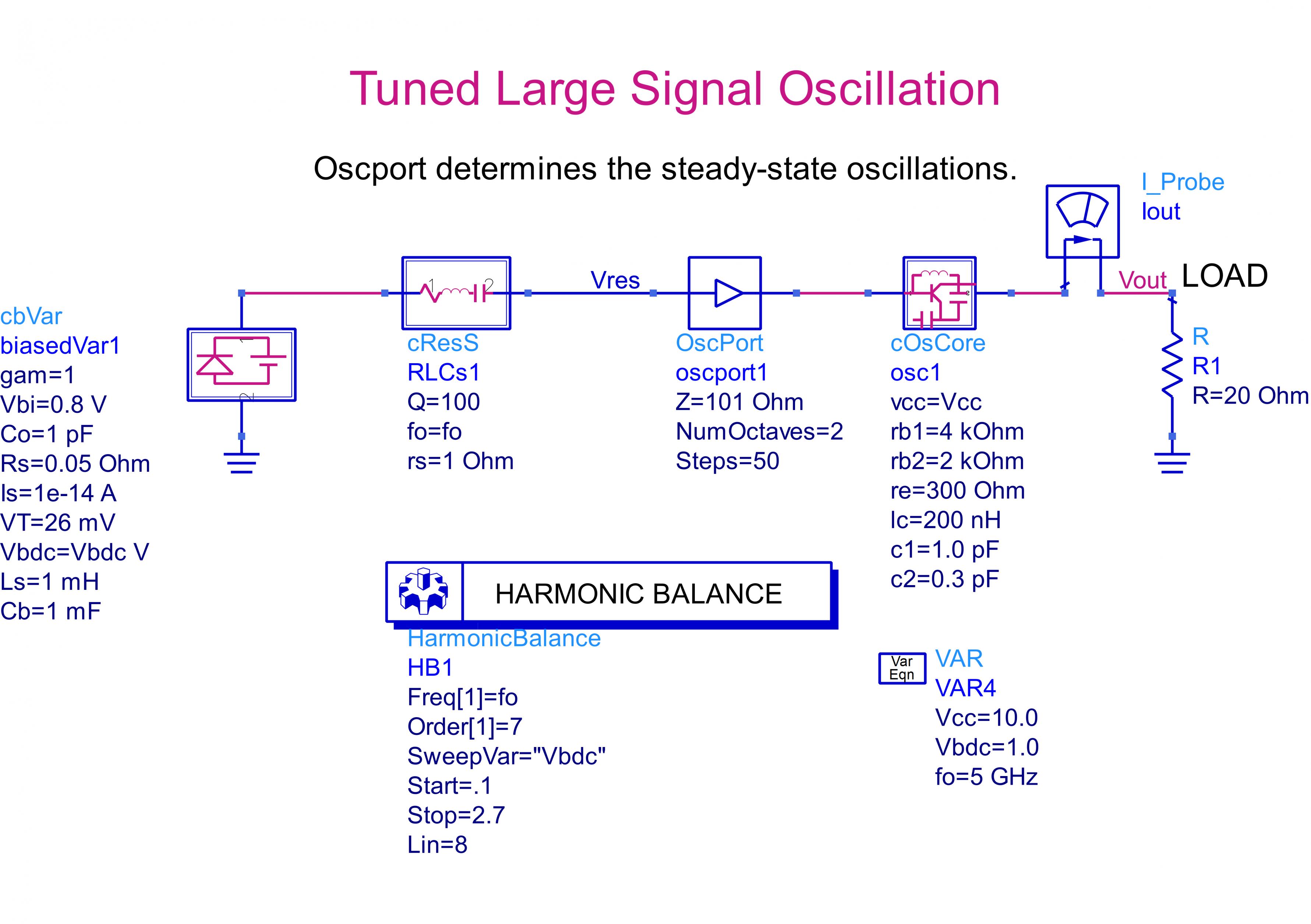
You can also use "Oscillator Design Guide" in ADS.there are many "templates" for such kind of simulations.It's really simple.
You will create a OSC testbench, you define your variables in HB controller then run the simulator.
I don't think there are particular tutorials for your target.( Maybe there is but I don't know )
I used tuned frequency oscillator and frequency pushing. I define first my oscillator as a symbol and i define the ouput terminal, however i don't know where is the input terminal. Can ou help me to specify the input node. After that, i should specify the control voltage as a terminal which will be sweeped after. Thank you for you hell
You have a VCO with 2 port.
One Port is the Output and other one should be the Vtune Input.
The Output is connected to a Load, Vtune is connected to a variable DC Voltage Source.
All you have to do to sweep this DC Voltage from lowest value to highest value and observe the VCO Frequency.
That's it..
Thank you, i replace the oscport by my test bench circuit and i connect the output to the load and the control voltage to the input terminal. However, when i simulate, an error is generated'No component named oscport1was found when lookin for oscport'. Knowing that i called my circuit oscport1 but it doesn't know my device. What can i do to correct this error.
Post you simulation schematic here..And HB Controller-Oscillator Settings capture
There are the shematic and the error. What can i do to simulate correctly this template


I think you set-up has some errors.It should look like
Delete your set-up (ans sub-circuits) and re-create it. If the problem persists, check your library/design guide installation because when you call "Voltage Controlled Oscillator-->>Tuned Frequency oscillator" template, ADS has to create automatically this template.Otherwise there is an installation or license problem.
But first of all, Read-please-carefully Oscillator Design Guide part of ADS help.Because there are many option and choices and find the optimum one for your application.
- Tuning Selectivity Factor
- Tuning of varicap diode in a magnetic loop antenna based on modulating signal
- Questions about S22 calculation of frequency tripler in ads simulation
- MC145151/2 p2 calculation dip swich vs xtal divader
- How to calculate bandwidth for this circuit, including lower and higher cut off freq
- Re: Calculate Capacitance Value from Smith Chart