RF coaxial transformer
I am looking for a VHF wideband coaxial transformer (4:1) using a ferrite. I attached a picture of one of those transformers. I hope few of you are familiar with this component.
Could you help me finding a supplier ? I had a look and could not find any.
Thanks
Normally Minicircuits has wideband transformers, but they use twisted enamelled wire instead of co-ax
(it means the transformer can be smaller). Maybe they have co-ax ones too. Otherwise, a co-ax one can be made,
by purchasing the ferrite (an example supplier is Amidon).
I think it is custom made or you have to build it yourself. It isn't that bad to build one with your frequency spec.
Thank you.
If I use a 50 ohms coax cable and want to use it as a balun, what is the impedance value I get on the balances outputs if I use a 50 ohm load on the single ended side?
It should be 25 Ohm on each leg as seen from the input.
Could you give more details ? I don't really understand...
I upload some old articles relating to coax transmission line transformer (TLF) for your peruse. That will help later when you can't find the right impedance coax for your design so you have to look for alternatives.
Regarding your question, since it only stated the unbalance side & coax Zc, I just assume it's 1:1, hence my answer (as shown from Fig 6.12 the 1st balun config from the left, unless you mean something else)
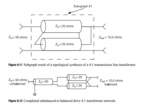
Thank you for those information, I need to go trough hit. I see this figure 6.12 but I don't really understand, because on the unbalanced output of the balun the metallic shield is connected to the ground, so on the balanced side, the impedance seen between the metallic shield and the ground should be a short, right?
True there is no DC isolation for this type of balun but a ferrite sleeve around the coax cable (which the diagram doesn't show and is always there) will present a high impedance to isolate the input & output at low frequency dictated by the ferrite material. At higher frequency, it becomes a transmission line.
I think you need to read more on this subject and there is plenty of materials available on internet. Here is one for you ...
One more thing to save you some troubles down the road, if you plan to do it yourself, the ferrite impedance calculated isn't that great and could be off 25% due to manufacturers variation of process. And that's directly from an application engineer of Feroxcube. So pick one manufacturer, build one, measure it yourself and stick with that one.
They used -probably- 50 Ohm semi-rigid coaxial cable to build Balun/Impedance Transformer and ferrites have been used to improve/wider bandwidth.
Nothing special in this picture.You can make it by yourself.
Yes but I don't understand why you get 25 ohms on the balanced output of a 50 ohms coax cable loaded by a 50 ohms load. Could you give a start for the derivation ?
Hi all,
I have the following output matching network of a power amplifier. The output balun has a weird configuration at the output.
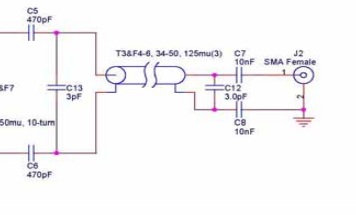
Why do they had a capacitor between inner and shield connectors?