RF transmitter with putty test ?
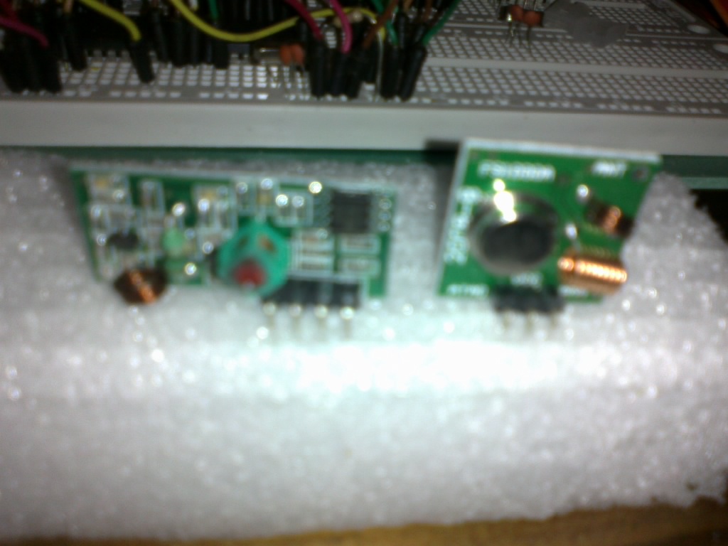
I want to test my RF module like this one :

With MCS 51 as a receiver and PC as transmitter (serial port) I connect TX pin from PC to Data on transmiter module, is it possible ? I tranmit using PuTty and receive with MCS51(I connect data into RX or pin 10 on AT89S52),
I haven't seen any responses,
Anyone has ideas ?
thanks
Here's the code:
#include <REG51.H>
#include <stdio.h>
sbit LED1= P0^0;
sbit LED2= P0^1;
   unsigned char Serial_read() {

    SCON  = 0x50;		        /* SCON: mode 1, 8-bit UART, enable rcvr      */
    TMOD |= 0x20;               /* TMOD: timer 1, mode 2, 8-bit reload        */TH1 = 253;                 /* TH1:  reload value for 9600 baud @ 11.0592MHz +/- 3.5% error  */TL1 = 253;TR1   = 1;                  /* TR1:  timer 1 run                          */
    TI    = 1;                  /* TI:   set TI to send first char of UART    */display_wait();  printf("\n Enter `a` to continue \n");
        while(!RI);
        RI = 0;
        return SBUF;
}

main()
{
   unsigned char serial_char;
        while(1)	 {	 serial_char=Serial_read();	 switch(serial_char)       {	   			 case 'a':			        LED1=0;
LED2=1;	             break;			 case 'b':			        LED1=1;
LED2=0;	             break;
 			}	}
}
Just search for your own post - you did it last year!
https://www.edaboard.com/thread231863.html
Why would it be any different now?
Mate,
It's different because I'm using a Radio Frequency to transmit the serial data from my computer into microcontroller,
Do you have ideas ?
The last year one was using serial cable...
If your RX/TX can handle the bitrate that you need, and if they have the same voltage levels to match the rest of your circuit, then
it is no different. The datasheet for the RX/TX will tell you this detail.
I need RS232 for voltage level ? and 2400 baud speed ?
---------- Post added at 15:31 ---------- Previous post was at 15:05 ----------
Spec that I can find out :
Receiving module technology parameters :
The product model MX-05 V
Working voltage: DC5V
static current: 4 MA
Receive frequency: 433.92 MHZ
Rx sensitivity:-105 DB
Size: 30 * and * 7 mm
external antenna: 32 CM single polishing, spiral around
Transmitter Module technique parameters :
The product model: MX-FS-03 V
transmitting distance: 20-200 meters (voltage different, the different effect) working voltage: 3.5-12 V
size: 19 * 19 mm
operating mode : AM ,transmission rate: 4 KB/S ,transmitting power: 10 mW ,
transmitting frequency: 433 M ,External antenna: 25 cm common multicore or single core
Pin from left to right: (DATA; VCC; GND)
---------- Post added at 15:35 ---------- Previous post was at 15:31 ----------
complete spec :
TX Technical Specifications:
A. Working voltage: 3V~12V
B. Working current: max≤40mA (12V), min≤9mA(3V)
C. Resonance mode: sound wave resonance (SAW)
D. Modulation mode: ASK /OOK
E. Working frequency: 315MHz-433.92MHz, customized frequency is available.
F. Transmission power: 25mW (315MHz at 12V)
G. Frequency error: +150kHz (max)
H. Velocity: ≤10Kbps
I. Self-owned codes: negative
J.Aerial Length: 24cm (315MHz), 18cm(433.92MHz)
RX Technical Specifications:
A. Working voltage: 5.0VDC +0.5V
B. Working current:≤5.5mA (5.0VDC)
C. Working principle: single chip superregeneration receiving
D. Working method: OOK/ASK
E. Working frequency: 315MHz-433.92MHz, customized frequency is available.
F. Bandwidth: 2MHz (315MHz, having result from testing at lowing the sensitivity 3dBm)
G. Sensitivity: excel –100dBm (50Ω)
H. Transmitting velocity: <9.6Kbps (at 315MHz and -95dBm)
I just received some of these and will try them out "soon". I suspect that the transmit and receive data levels are comparable to the supply Voltage - for the 5 V receiver standard TTL levels should work. If you power the transmitter at 5 V then it should be standard TTL also. Some demo code etc. is available at http://forum.hobbycomponents.com/vie...hp?f=39&t=1324 .
