Differential active loop filter
Can you please tell me how can I calculate differential active loop filter components shown below?

Thank you
Looking at the lower half of the schematic...
The series resistors and capacitor form a high-frequency-diverter on the '?n' signal. However it becomes interpreted as a low-pass filter by the op amp circuit. That is, according to the (simulated) output.
Values must be chosen to create the desired rolloff curve.
That only covers one aspect of the circuit.
I guess I'm cheating by using a simulator. There's a lot of variables in this circuit. A lot of uncertainties. Such as the input signals, their relationship, their polarity, etc.
Let R1=Z1 and R2+1/(sC2) =Z2
Vo = φn*(Z2/(Z1+Z2)*(1+Z2/Z1) - φr(Z2/Z1)
I'll ... simplify the above.
Vo = (φn - φr)*Z2/Z1=(R2+1/(sC2))/R1
Vo = (φn - φr)*(sR2C2+1)/sR1C2 where s=j 2pi*f
Does that help?
Diff active loop filter? Any detail example? Such as a detail synthesis, VCO, PLL etc.
I had done many single input PLL using ADISIMPLL, but never used diff PLL.
SunnySkyGuy thank you for this equation, I have seen it before. But from this, how can I find R1,C,R2 values? I need an equation like passive filter components do with Icp, Kv, etc.
I have seen an equation like
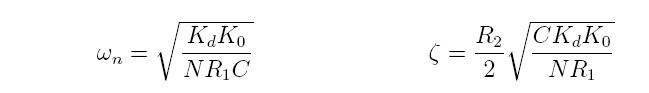
where fn=loop bandwidth but my circuit doesn't respond according to this equation when I change the capacitor and resistor.
BradTheRad, I wanted to use a simulation tool like ADISimPLL but it doesn't have a topology like that. If you know some kind of simulation tool to put this, I would be very glad. This would be the easiest method I prefer.
tony_lth, the synthesizer is HMC698lp5. VCO has single input and Kv=12MHz/V. Using an opamp for differential active loop filter seen on the picture that I have posted.
It's Falstad's animated interactive simulator. Free to download and use at:
www.falstad.com/circuit
Click Allow when you see a message asking permission to load the Java applet.
To get a grasp on the interaction of R1 & R2, substitute a potentiometer, say 50k.
Try this and let me know how it works.... learned scholars pls correct my work... for radian conversion may be wrong....
ωn=√(KpKv)
. . . . √(Nτ1C)
where τ1 = (R1+R2)C [s] = Kp Kv /ωn2
where Kp is the phase detector gain in [volts/radian], Kv is VCO gain in [radian/volt-second] for VCO fractional divider=N
so Kv=12MHz*2π [rad/V-s]
ζ = 1/(2ωnτ1) + ? ωnτ2 where τ2 = R2C
o--/\/\/\/\-- x ---||----/\/\/\/\---o
. . . R1 . . . V . . C . . . R2
I recall using R1/R2 is = 5 to 10
The problem with this analysis is that it is an approximation due to the fact that the Phase detector is limited in output for phase error so gain reduces as frequency error increases for type II detectors. Also error amplifiers and VCO control voltages are limited, so that the analysis has constraints. Consequently dual gain filters for capture and lock mode have performance tradeoffs for faster capture or reduced phase jitter are often used as well as other signal conditioners in software or hardware for rapid error correction to acquire lock.
Some old fashion PLL circuits MC145152 have differential CP outputs.One output clocks up and the other clocks down depending on the phase leading or lagging...
Bannerjee's Deansbook explains all the details of the computation on diff. PLL Loop Filters.It's possible to find some applets to calculate them on the internet..
Hi, SunnySkyGuy,
How to set the phase margin?
Thanks.
One chooses critically damped as a starting point ζ =0.7
Then verifies design by testing under worst case VCO drift using BODE Plots or time analysis using step response and overshoot.
Hi, All,
Attachment is the typical PLL application circuit using HMC698LP5 PFD and HMC529LP5 VCO.
So I calculate it in the MAtlab and found the following questions:
1. I can't certain that Kvco=150MHz*2pi, is it right? Or any other value?
2. There is a C1=270pF in it, how it affect the PLL loop bandwidth and zuni coefficient?
3. From SunnySky equations, I got two zuni, 1st is 0.0858, too small? And zuni2=12.48 too big? And PLL loop bandwidth is 1.86MHz, too big?
Here is my Matlab code:
Code dot - [expand]
The circuit is from Hittite HMC698LP5 datasheet.
I doubt the Zuni equation is right or not.
Hi,
Who can help me on how to calculate the transfer function of the foresaid PLL?
Or who can recommend a book or documents for the transfer function from real RLC components topology?
Many thanks/.
After review my textbook, I finally knew how to calculate it. It's about 20 years after I studied it in college, so long that I almost forget it.
Thats normal. I've forgotten 99.99% of the details since I left U of Mb '75. But i remember all my designs and experiments.
But I still have some trouble to understand the feedback transfer function, now I can master passive filters, but for active, it is a little different.
Such as following picture, which is feedback, Assume that Z12(s) is the impedance transfer of C1, R2, C2.
how to express the transfer function?
I know the feedback expression is H1(s)/[1+H1(s)*H2(s)],
but I am confused about the feedback.
Many thanks.
For simple, only R3 and C3 are considered, R4 and C4 can be omitted.
sorry, I made a mistake yesterday so that I doubt my idea, actually now I know how to do it.
Differential loop filter 相关文章:
- Loadpull for Differential PA
- How come differential cascode structures affect on PA characteristics?
- Microstrip differential impedance depending on line width
- Differential Input For Dickson Chgarge pump Rectifier
- Multiband Differential Rectifying Circuit (re symmetry or not)
- Differentially-Fed Rectifier