Using some capacitors before a transistor to bias it for RF power amplifiers
I am designing a Class-E power amplifier. As I looking at these circuits there are some capacitors on the root of biasing transistors. Could you please say why these capacitors have been used and how we should calculate their value to use them in our circuits?
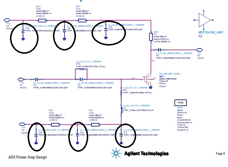
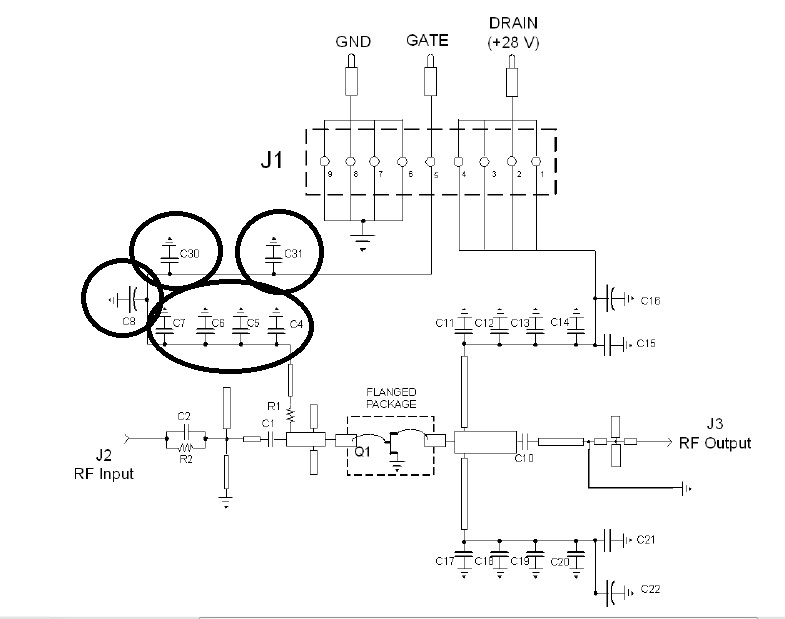
I have attached two circuits. The first one is from Agilent and the other one
Thanks a lot
The capacitors with inductors form low-pass filters, to prevent RF and AC signals coupling back to DC power supplies.
Using several capacitor values in parallel is recommended for blocking a wide frequency spectrum. High-capacitance capacitors (like 1...100 uF) have certain inductance, so using ceramic capacitors in parallel improves filtering for a wide frequency band.
Good blocking is needed due to low-impedance amplifier structure.
I think it is helpful to clean the DC input by filtering with it.
You are right my friend, but, how exactly we should calculate their amounts? For example, consider we have 28 volt supply voltage for drain and -2.5 volt for gate and we are working at 2.3 to 2.3 GHz frequency band (Second Photo).
As E-class amplifiers also use PWM to operate, it is a good idea to design a low-pass filter that rejects all unwanted spectrum components (first diagram) The second diagram only utilizes several capacitors in parallel to filter the RF spectrum.
Where inductors are used, they form poles in filter response as needed. You will have to study filter design to understand all details.
transistor capacitors RF 相关文章:
- Cree??s CGH40010F transistor
- How to include RF Transistor Vendor Kit in Advanced Designed Design(ADS)
- Which transistor need to be chosen for designing KU-Band LNA Design high gain, low NF
- Design of LNA using CMOS transistor
- Can you help me get S-parameter file of HJFET transistor
- what type of biasing configuration is this transistor using?