BPF insertion loss increases with input power level... why?
While not technically RF frequency, the 1 MHz signal in question is my IF output of my RF system, and I thought I might have a bit better response posting this here, rather than in the analog section.
I'm mixing together 1497 MHz and 1496 MHz to get a 1 MHz output IF, filtering and amplifying, prior to transmission. I used the Raltron bandpass filter calculator, built it using close component values, and the filter response is actually really good.
My problem is that as I get close to 0 dBm, my insertion loss starts to increase. I built the filter standalone and swept it with the NA, and took screen shots. You can see that as I increase power from -20 dBm to 3 dBm, my insertion loss increases by 0.1 dB, and continues to worsen as the power increases (for picture taking purposes, my NA power is limited to 3 dBm).
My question is... why? At 3 dBm, my inductors shouldn't be anywhere near their saturation threshold, and as a test, I wound my own inductors on toroids with cores from Amidon, which certainly should be below the saturation threshold, and still saw the same effect.
My output spec is +/- 0.1 dB, and I'm right on the threshold at 3 dBm, and above that I don't meet it. I'm stumped as to what I can do to fix this. I have done some google searching, but can't find an explanation online as to what the issue is. I've always been taught that passive filters have a very high P1dB and IIP3, so I don't understand why I'm having a problem at such a low power level.
Any suggestions?
Calculator:
Schematic:
Increasing loss with input power:
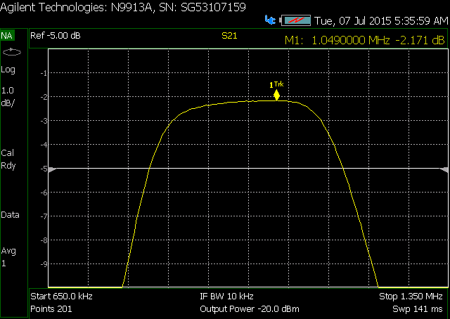
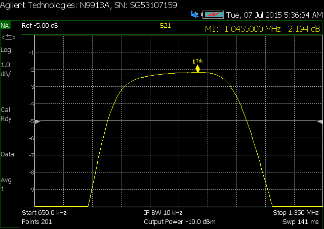
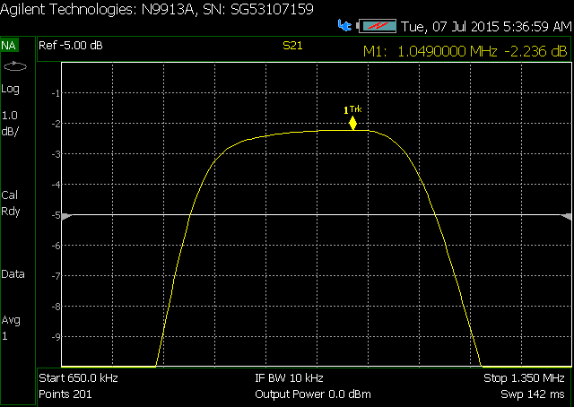
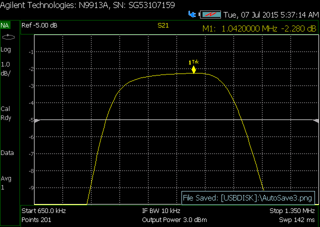
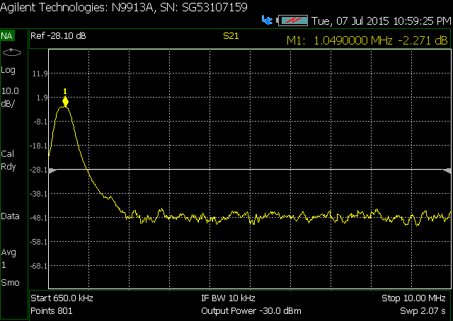
Expanded frequency response of filter:
Can you look at the 1 MHZ component prior to the filter. As you say passive filters have basically a thermal limited power limit, like watts if not tens of watts. I suspect your mixer or your instruments.
Frank
I don't know what Amidon cores you are using, but to get 0.1dB increase in insertion loss is more likely due to the saturation of the ferrite cores.
Filters built with ferrite cores have a soft roll-off in insertion loss vs power (starting with low power levels) and only when reaching a certain power the magnetic flux (saturation) increase dramatically.
The filter was laid out on both a boardhouse-made pcb, as well as a hand made one:


The standalone one has been swept with two separate NA's, as well driven with a 1MHz source and output measured on a Spec An. It exhibits the same issues on all setups, so I don't think it's test equipment dependent. Additionally, the PCB-based filter was hooked up originally as so:
It's being driven by a Norton Common base xformer feedback amp. Ignore the output op-amp since that's no longer used... the output of the filter goes to a pad, which then goes to the output connector. If I drive the load directly with the norton amp, the output is linear. Introducing the BPF causes the non-linearity. I put the pad between the amp and the BPF in case I was having mis-match issues, and have tried setting it to different values (as well as bypassing completely), and it hasn't had any positive effect on the linearity.
Original Component selection is as follows:
2.7 uH TDK NLV32T-2R7J-EF: 290 mA rating, 70MHz SRF... according to their website, it's well below saturation at 100 mA current
47 uH API Delevan 1210R-473J : 163 mA, 13MHz SRF... can't find a sat current rating
10000p Kemet C0805C103F1GACTU
560p Kemet C0805C561F5GACTU
Although I can't find a sat current rating for the 47uH inductor, I did look it up for a similar one made by TDK (same family as my 2.7uH), and the inductance is fairly linear through 55 mA of source current.
Even putting 10 mW into the BPF, the inductors aren't going to see current anywhere near those levels.
As for the Amidon cores, I used several different iron core toroids of 1 & 15 material to make my own 2.7 uH inductors, and verified their values with a LCR meter. Unfortunately I don't have a large enough core on hand at the moment to make a 47 uH inductor (would need 70-ish turns on my T37-1 toroid, which is the largest I have on hand). So I guess the test with the hand-wound cores isn't fair, because the one most likely to saturate, I couldn't recreate on an appropriate core. I am attempting to find a toroid in my "stock" now to make the center inductor.
If one of the cores goes into saturation, for sure the first one would be the 47uH core. So, for this inductor you have to spend some time finding a good core.
The resonators can have rather high Q ... have you checked (simulated) the actual inductor currents?
Yes... I did find a bigger toroid (3/4" OD) and wound a 50 uH inductor on it, and the effect was less, but still had an effect nonetheless
^ this occurred to us (myself and coworker) this morning. Simulation shows current through the 47 uH to be quite a bit higher than I though, but not to the level that I'd expect to see significant inductance rolloff... assuming 1V peak input, it was on the order of 10 mA or so... I wouldn't expect to see rolloff until at least twice that.
Funny I see a double tuned filter coupled using two low impedance high Q filters coupled by a higher impedance mid-section to widen the bandwidth., so each Q much higher than 3 with high impedance on the 47uH and low impedance on the 2.2uH chokes resulting in attenuation after the 560pF and then a boost in current again on the 2nd 2.2uH.
IS that what you intended?
It may not actually be full blown core saturation, but the BH curve is far from linear, and the dynamic permeability, eddy current loss, and hysteresis loss all change with drive amplitude.
Have you tried using one of the RF powdered iron toroids instead of ferrite ?
The saturation flux density is several times that of ferrite, and with the right powdered iron "mix" the operating Q at 1mHz can be optimized.
http://www.micrometals.com/downloads...0Issue%20H.pdf
I have simulated your filter in Microwave Office to see the currents. Power is 10dBm, currents in graph are mA.


I clearly hadn't considered fully how the core would react as amplitude increased, especially the nonlinear response.
I haven't tried an iron toroid for the 47 uH... unfortunately I don't have one on hand that's big enough, but am going to order a couple to play with. The only "big" toroid I have on hand is a ferrite.
While I admit to being out of my element, I am capable of learning. I've already admitted to using the "cookbook" solution, as I took a screenshot of the calculator that I used to generate this filter (in one of my earlier posts). My ASSumption is that the result would be the same if I was looking it up manually in the Zverev filter tables. So I didn't really "intend" anything except to get to the end result, and rather than look things up manually, I just grabbed an online calculator that I've used in the past for stuff.
Aside from limitations of my components, if you have a suggestion for improvement, feel free to state it, I'm here to learn.
Thank you very much for this! The fact that your results are approx double of what I got tells me I screwed something up.
This is my sim
so the filter appears to have very high loaded Q resonators and the coils are becoming non-linear.
You could put a transformer at the front, and another one at the rear, to transform the filter match impedance up. Say you designed the BPF for 100 ohms match, the currents flowing in the coils would be similarly lowered. (at this narrow bandwidth, the "transformer" might be a simple L-C network)
I did simulate this, with tapped capacitor transformers before and after the filter, going from 50 to 75, and back again. As impedance increases, the inductor values increase, which results in a lower saturation threshold, and only modest current reduction.. IE, the series coil went from 47 uH to 79 uH (68% increase), while reducing current from 20 mA to 16 mA (20% decrease). Also, the current in the shunt inductors of the transformers is quite high (300 mA, if my simulation is correct).
I tried the transformation with a tapped inductor xformer instead and I'm getting weird results, so I have to double check the math in that. That said, my calculated values for the tapped inductor were a lot more reasonable... everything was nano level...
Volker's simulation is exactly what I expected. what are your source & load Z , signal levels and Modulation BW?
the simplest solution was implemented in the 60's with 5 transistor AM radios using a double tuned IF at 455 kHz transformer with tuneable ferrite slug for coupling to achieve high gain at 15 kHz BW . Do you need wide BW? What about phase distortion? Group Delay distortion?
it still might help a little since the loaded Q of the shunt L-C's is much higher than that of the Series L-C.
You COULD make them all shunt L-C's, and only have series C's (i.e. 3 shunt L-C resonators). then for sure raising the impedance to say 100 ohms would help. But more importantly, you can vary the coupling with the series C's and maybe not need such high loaded shunt L-C's, which would relax the currents flowing in the shunt L's.
So I would try the filter :
Series C
Shunt LC
Series C
Shunt LC
Series C
Shunt LC
series C
You are taking advantage of the fact that you can get very high Q porcelain caps (for both series and shunt positions), while it is hard to get very high Q inductors. Also by adding series only capacitors, you should be able to achieve a higher Loaded Q with lower unloaded Q resonators
