Losses in a microstrip resonator
As a chemist, a part of my job is to use RF circuits to follow chemical reactions. It is a very powerful tool but, since I have no solid training in RF, I sometimes have difficulty with some concepts.
I understand that if I measure the reflection (S11) and transmission (S21) coefficients of a microstrip with a V.N.A, the values will follow this equation :
|S11|2 + |S21|2 + losses = 1
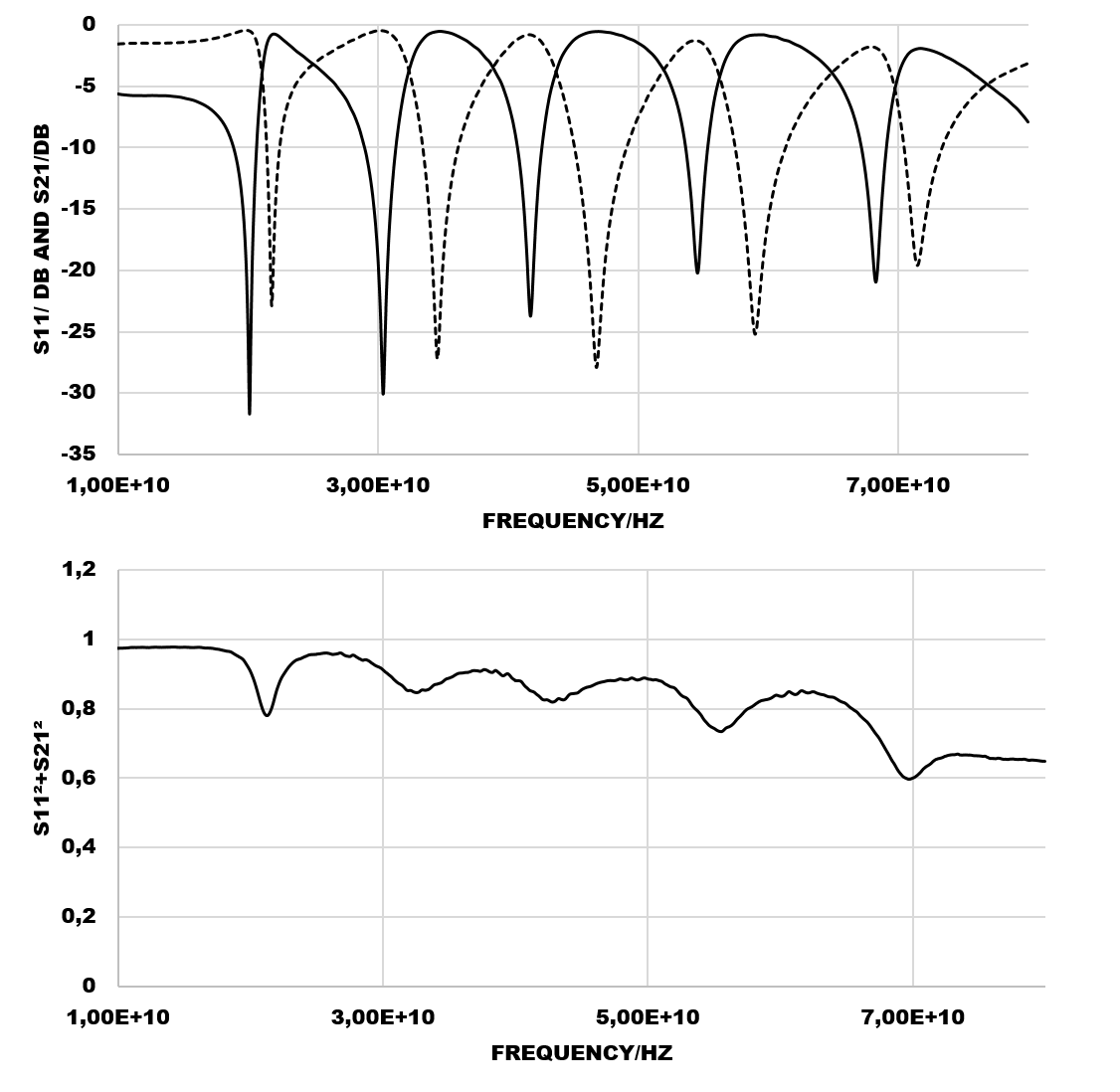
The circuit that I use is a microstrip coupled with a spiral resonator. It has 6 resonances between 10 and 20 GHz. When I calculate |S11|2 + |S21|2, it is is nearly equal to 1 before the first resonance, then it decreases to 0.6 with "peaks" within the frequency range. I noticed that the maxima of theses peaks in S112+S212 are located when S11 is equal to S21.
I know that this means I have strong losses in my circuit but can you tell me what are the very likely causes of theses losses? Can they be due to a poor calibration? Or maybe a bad adaptation of the circuit?
I joined S11/S21 plots (S21 is the dotted line) and the S112+S212 plot so you can see :
Thank you very much!
There are many sources of loss in RF circuits, especially resonators.
Depending on the substrate used for the microstrip, losses in the dielectric can become exceedingly important at higher frequencies (> 10 GHz). The quality factor (Q) of the resonator will have a strong influence as well. There may also be other effects such as radiation losses from the resonator and/or microstrip. Additionally, many microstrip SMA connectors are only rated up to 18 GHz - ensure that yours is supposed to be used up to 20.
Good Luck!
I believe this is real. In highly accurate EM filter simulations that include conductor loss (but no substrate loss and no radiation loss), I also see this loss peak at the edges of the pass band. My understanding is that we have highest current on the resonators at these frequencies, so the conductor loss peaks.
Thank you guys!
This is interesting. Can we say that the "true" resonances of the system are located at these S112+S212 extrema?
That is an assumption, not a fact. What about radiational losses? A resonator, especially at high frequencies, can act like an antenna, and energy is simply lost to free space. you would not see radiational losses on a network analyzer measurement, as it does not return to either port.
In order to make it non-radiational, you would need to confine the resonator inside a metal housing with dimensions so that it is like a cutt off waveguide.
You might be able to use coplanar microstrip (the type with ground plane on the top to either side of the main line. That has little radiational energy, and might not need to be enclosed in a metal box. Your resonator, or course, would have to be made of coplanar microstrip elements.
Losses microstrip resonator 相关文章: