Understanding of the Beat Signal of the Radar
I am confused about the beat signal of the radar when I read some IEEE papers.
I have the following questions:
1. What is the purpose of the beat signal? To avoid flicker noise?
2. Beat signal only fit for LFMCW radar?
3. How to conduct beat signal in Radar? Is it the 1/T, T is the period of the waveform?
4. Based FFT, range resolution is by Delta(R)=C/2.B, it seems beat signal has no relation with Delta(R), right?
That is all I can think,
Thanks for your help.
Please read Skolnik, Principles of Radar. The FM-CW radar principle indicates that the transmit signal mixer (correlated) with the receive signal, due to time delay between the two, generates the beat-frequency output. The beat frequency also depends on transmit frequency.
Signal power must be adjusted so that the received signal exceeds the thermal noise level, therefore it includes antenna gain and propagation loss.
Best read the textbook indicated which includes all basics.
From what i learned beat signal is just low frequency result of mixing. Beat signal is IF output of mixer. Assume we have one oscillator with frequency F1, transmit and receiving antennas, power divider and mixer. In case of FMCW radar the farther reflecting object is, the higher beat frequency is. For near placed reflecting objects beat frequency will be still small and distorted by flicker noise. In case of CW doppler radar low speeds will be distorted by flicker noise too. If we add separate oscillator for receiving mixer (F2), then all mixing results will be shifted by DF (DF=F1-F2) amount. And this amount called beat frequency too, and i think it is confusing. So frequencies that represent near distances or low speeds will be moved by DF out of flicker noise area. Never saw or read about somebody used second oscillator for FMCW or doppler to avoid flicker noise. It seems too complicated to me. There are few manufacturers of integrated VCO+mixer ICs todays, and all of them use single oscillator for transmit and mixing.
https://en.wikipedia.org/wiki/Beat_(acoustics)
https://en.wikipedia.org/wiki/Heterodyne
From what i read from this pages i can say that there are too many things can be called beat frequency. For example when summing two equal signals with different phase shift there can be amplitude beats, in many peapers there are FMCW beat frequency. And it is confusing. Cause of frequency shift is different (distance time delay, doppler), but mixer works equal in doppler and FMCW cases. It have some LO input, RF received echo, and IF output.
It is not clear what the question is. Usually there are multiple reflectors, and their frequencies are mixed, so some method like FFT or wavelets are used to extract frequencies. In case of single reflector, like point reflector, you can use simple methods like zero crossing counter to estimate T and then F=1/T.
There are some good formulas on radar signal processing i read somewhere. The most important i learned from them is those things: the higher oscillator frequency is, the faster you can obtain high resolution measurement. If you use FFT, T is usually fixed. It can't be too long, because signals are usually change frequency with time, so there must be some compromise between FFT resolution and T.
In case of FMCW the wider the bandwidth is, the faster is modulation is , the more precise result is. If your frequency is too low, then your bandwidth can't be too wide, because it will interfere with restricted bands. So you can see most powerful players, such as manufacturers of collision avoidance radars and similar things moved to 70GHz range, where you can use wide bandwidth, something crazy like few GHz bandwidth, where you have short single measurement time. At 70GHz you can get the same speed precision as at 20GHz but around three times faster. For example at 20GHz your system uses T=10ms and doing FFT. At 70GHz 3ms is enough to get similar precision. Drawbacks: need to use faster ADC, because doppler frequency shifts are much higher. But they do not worry about flicker noise, because at 70GHz any significant traces of it will be far away even from 1km/h. And as their aquistion speed is higher, then can interpolate and do other algorithms to improve data. It is like you play game at 10fps or at 30fps, of course you can react better at 30fps. Range resolution is just how far distance peaks will be in FFT spectrum bins, and how much is the noise. Making frequency modulation change more rapidly vs time moves peaks farther away, but requires wider bandwidth, higher ADC speeds.
I think this might be useful for you:
https://www.edaboard.com/thread342419.html
i think that circuit on this photos use two separate oscillators. One for transmit, other for receive. Second mixer may be providing additional constant frequency shift to move low frequencies out of flicker noise.

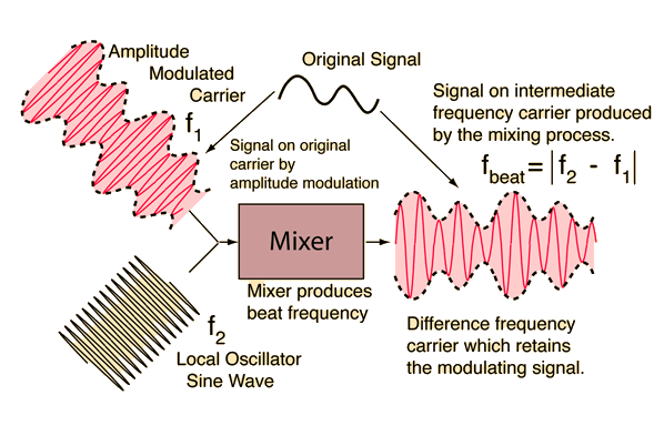
Attached image gives simple explanation.
beat means typically people use this term for mixing.
The above picture is not correct. In any mixer, due to its non-linear element(s), at the output (right side), not only the difference f2- f1 appear but many linear combinations of the inputs, f1 and f2, and also their multiples.
To make the output f2-f1 the only desired one, filters are needed. Such filters are missing in the picture.
Understanding Beat Signal 相关文章:
- Help in understanding the paper "Understanding Wide-band MOS transistors"
- Understanding of noise figure
- Need help understanding an LNA design method
- Understanding how to translate standards to system requirements
- S21 graphs, comparison and understanding
- (Understanding) Problem: Load-Pull in Cadence/Virtuoso
