I don't understand impedance matching of the RF circuit in the schematic
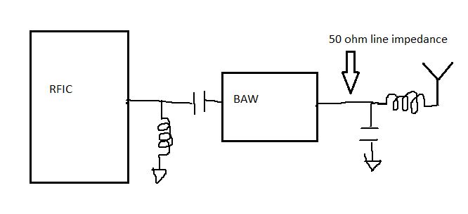
Ok, refer to attached schematic I drew, I do not quite understand why the design is like this, I have below doubts:
1. are the caps and inductors for the purpose of impedance matching? If yes, is it still necessary to design the 50 ohm impedance trace at indicated location?
2. What is the difference of LC impedance matching and 50 ohm trace design impedance matching?
3. is the impedance matching for signal integrity or max power efficiency, or for both?
4. The BAW filter will change electrical signal to acoustic signal, what is the purpose of such conversion? And how to realize narrow bandpass fitering with BAW?
5. If all the traces are very short, e.g less then 1cm, still need impedance matching or not?
Sorry I asked a lot of questions, but I am very curious about RF knowledge.
Yes.
BAW requires 50ohm terminations at both sides.
What do you mean by "50 ohm trace design impedance matching" ?
If you mean "signal integrity" as spurious emission, for both.
To make small filter.
Consider wavelength of 1GHz as both electrical and acoustic signals.
Latter is very short.
Rather broadband is difficult.
Still need impedance matching, since BAW requires 50ohm terminations at both sides.
Hi, Thanks for the quick reply, what I mean by 50 ohm trace design is to design a 50 ohm characteristic impedance trace in the PCB for that rf signal, in which the PCB stack up, PCB trace width, and some other factors are considered.
If line length is enough short, e.g, less than λ/10, 50 ohm characteristic impedance line is not required.
Completely different.
Former has no direct relation to characteristics impedance.
However, the BAW itself is usually not matched to 50 Ohm. The 50 Ohm are obtained by BAW + matching components.
This means that internal 50 Ohm line between BAW and matching components is not correct anyway, the interface to 50 Ohm is outside the [BAW + matching] block.
What frequency? Impedance controlled transmission lines have an effect when the line length is > 1/10 wavelength. Wavelength must be calculated including the substrate influence, so it is smaller than wavelength in air.
Hi Volker, thanks a lot for the explanation. So now I understand BAW's RX/TX and Antenna port is not designed to have 50 ohm impedance, thus needs external matching elements(caps and inductors) to achieve so. But if I say the signal line is less than 1cm, signal frequency is 2.4GHz, so we do not need LC match for BAW's I/O ports, as well as PCB trace characteristic impedance design, is this true?
Or still need because even though signal integrity is not a problem, but we need to maximize the power efficiency, both LC elements and PCB trace design are needed even signal line is very short?
Hope you can explain, thank you!
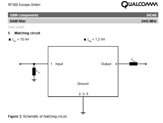
Your BAW is not same as this thread.
No.
Your BAW has to be terminated by 50ohm//Lp1 and 50ohm+Ls4.
No.
If we adopt your BAW for figure in start of this thread, BAW means including Lp1 and Ls4.
Operation frequency.
You can not understand BAW at all.
Volker's explanations are completely wrong.
BAW requires correct termination.
In your case, 50ohm at both sides.
Need LC match for BAW's I/O ports.
LC elements are required.
50ohm impedance line is not required.
Consider case of a direct connection to 50ohm-Antenna without BAW.
Of course, sweetheart. You are the only true expert. Good luck!
Hi Volker, I want to hear fro different opinions, I would admit I understand your explanation more then the other one, can you help to reply on my previous question? Thank you so much!
Ask @pancho_hideboo for an answer.
He is behaving like that in all his threads.
Please, I need your help, try to listen to me instead of him, I really hope I can find answers based on scientific truth.
I'm no RF/uWave expert like some of the people here, but pancho needs to learn some manners. Being this rude all the time to everyone is not sustainable.
I would think both pancho_hideboo and volker@muehlhaus are nice guys. It is also good to have some disputations. It is the purpose to have this forum. Of course personal insult should be avoided.
BAW is a very narrow band passband filter and usually needs external impedance matching network to have 50 Ohm impedance at both ports. To have 50 Ohm impedance is to make the connection with other components easier. In your case, your transmitter and antenna are both 50 Ohm, you then of course would like the inserted filter to have 50 Ohm input/output impedance. This will lead to the maxim transducer power gain.
About the transmission line impedance control. For long line, no doubt the impedance must be strictly controlled. But special care is still needed even for short track. As a rule of thumb, a short thin track can be regarded as small parasite inductor in series, a short but fat track (for example a component pad) can be modeled as a parasite shunt capacitor. The shorter the track, the less parasite effect. So in your case, you should place the impedance matching L/C as close to BAW as possible in layout. Then use strictly impedance controlled track to get connection with TX and antenna.
100 % agreed with you. I myself had issues with him.
EDABOARD managers turn a blind eye to his behavior and nothing can be done in this case unfortunately.
The forum is moderated by volunteers, not managers. Be pretty sure that they monitor divisive talks like this and try to enforce forum rules. Censorship isn't the preferred solution however. You can delete obviously insulting posts or even ban notorious offenders, but you don't change the demeanour.
If you feel that answers to your posts are inadequate, paternalistic, near to insulting or otherwise borderline, it's probably best to ignore it.