Questions about PA simulation in ADS
I have used ADS before and I don't use it right now. Sorry for I can't help you.
So I have an idea, why don't you upload your project come here ?
Follow your pictures, perhaps some information has been hidden and other cannot re-build your circuit.
Your original project can help other can check and answer easier.
thanks for your idea, xandeyes. the project is big and involves with a specific library. Sorry for not uploading here.
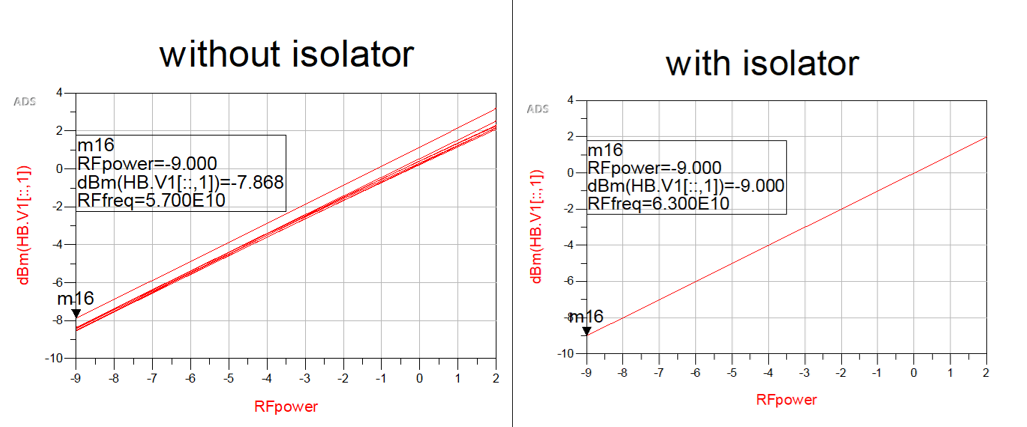
dbm() function is only valid for real characteristic impedances by default.In fact dbm() function syntax should be as follows
dbm(V,Z) -> Z can be real or complex.Z=50 by default and Input Impedance of your circuit is not pure 50 Ohm real..
The correct Power that enters into the circuit should be :
P=0.5*real (V*conj(I.Probe.i)) or 0.5*real(conj(V)*I.probe.i)
thanks BigBoss, perfectly answered my question. I just found that P_probe can also measure power of any harmonics. Thanks again for your answer.
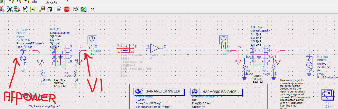
I was reading this post and wondered why did u inject another signal at the output of PA? Are you simulating some sort of load mismatch by using this? Can you explain what this simulation does?
Hello ktr, you are right. the source at the output is used to calculate S22 of the PA and it's a template for simulating the large signal of PA. you can obtain this by clicking in the schematic window: insert->template->ads_templates:S_ParamsLargeSignal. the template tells that" This source injects a small-signal into the output of the device, while the input is being driven by a large signal at the swept RF frequency. The injected signal is at a 1 kHz offset from the input signal." I 'm still confused and asked a question in '' https://www.edaboard.com/showthread....18#post1669218 ''. Untill now, no answers received.