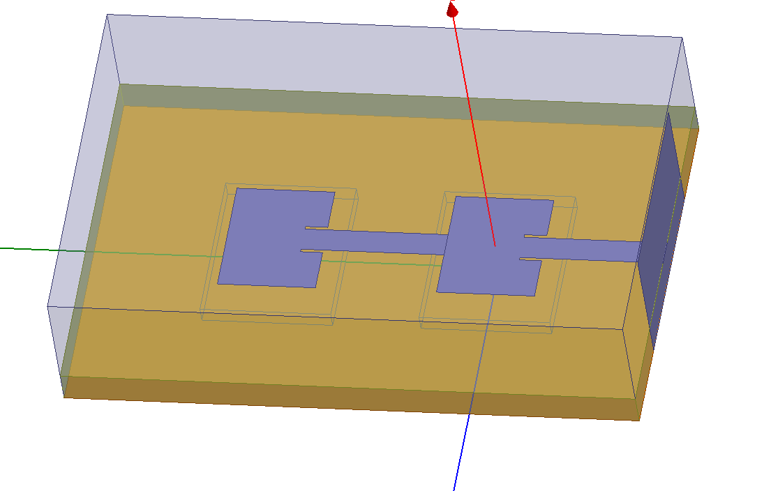
HFSS rectangular patch array help
I have my first patch done on HFSS and I was wondering if anyone can help design the array for this patch? I'm trying to generate an array to increase my gain and coverage! does anyone know how to do that? and what's the array factor for? I believe it's for this type!
Your help is greatly appreciated.
Thanks
sam
Hi ihamieh
it's very easy to design antenna arrays with HFSS. In the radiation section select Antenna Array Setup and insert array elements number and feeding. After analysis you can see Array Factor from results.
I hope it'll be helpful
Thank you Ali,
I'll try it tomorrow and I hope it will actually show how many patches? The thing is I'm trying to develop this design and I have to see the result as well as the actual design..
Thanks again..
Sam
Hi Sam and Ali,
With this kind of technique you can only observe the effect of making an ideal array (no mutual coupling). But in reality, specially in an microstrip array with small inter-element distance, the array factor formula which is used in this HFSS tool is not valid. You can see the degrading effect of mutual coupling on the rotation of antenna radiation pattern and a bit on the S11 when you perform a full wave simulation. Thus with the presence of mutual coupling, the element factor value should be adjusted.
Cheers
Hadi
Hello Hadi,
So, in this case this might work but it will provide some kinda of estimated value of the array factor. What are your recommendations to design an array antenna that include the actual design? I would like to provide my advisor with a design as well as a good simulation!
Please advice,
Sam
Hi Sam,
Actually I dont have enough information about your project, but my suggestion might be:
1- Design and Simulation of a single element
2- Design and simulation of an ideal array with the absence of mutual coupling. This can be done with Ali's suggestion and also theoretical formula
3- Next step (if you want to be more accurate) is to put at least two antenna elements next to each other (with the designed distance, let say (0.6Lambda) ) and perform a full wave simulation. In this simulation you feed one of the antennas and observe:
- S12 (mutual coupling between antennas)
- Deformed radiation pattern of the element (it is rotated)
Here you can make an estimation of the accuracy of your assumption in part 2.
4- Now to correct part 2 you can use the radiation pattern obtained in 3 as a element factor and again calculated you array radiation patterin as:
RadiationPattern= ElementFactor \times ArrayFactor
I guess this is a better estimation althoug it is not still perfect, becasue for example this element factor is different for elements inside and on the edge.
Cheers
Hadi
Hello Hadi,
Thanks for the info but I'm trying to generate one line array antenna and i'm not sure how to do it correctly? I wanted to try the master and slave boundaries but they have to be an exact size and they are not exactly similar!
Please let me know if you know how to do this? I'm still in my first patch and I have to build a bigger one!

Thanks,
sam
Sorry for late answer,
It seems that your simulation is OK. You just have to define the radiation boundary correctly.
Cheers
Hadi
rectangular HFSS array 相关文章:
- Feeding a rectangular wavegude with two pins
- 4 port rectangular waveguide switch
- How to set Rectangular wave guide port for nano size antenna in CST?
- Port of rectangular patch antenna HFSS
- Simulation Setup of Rectangular Dielectric Waveguide in HFSS
- [HFSS 13] Rectangular Waveguide wrong Sparameters.
