Port of rectangular patch antenna HFSS
This is the antenna and how the s11 parameter should look like
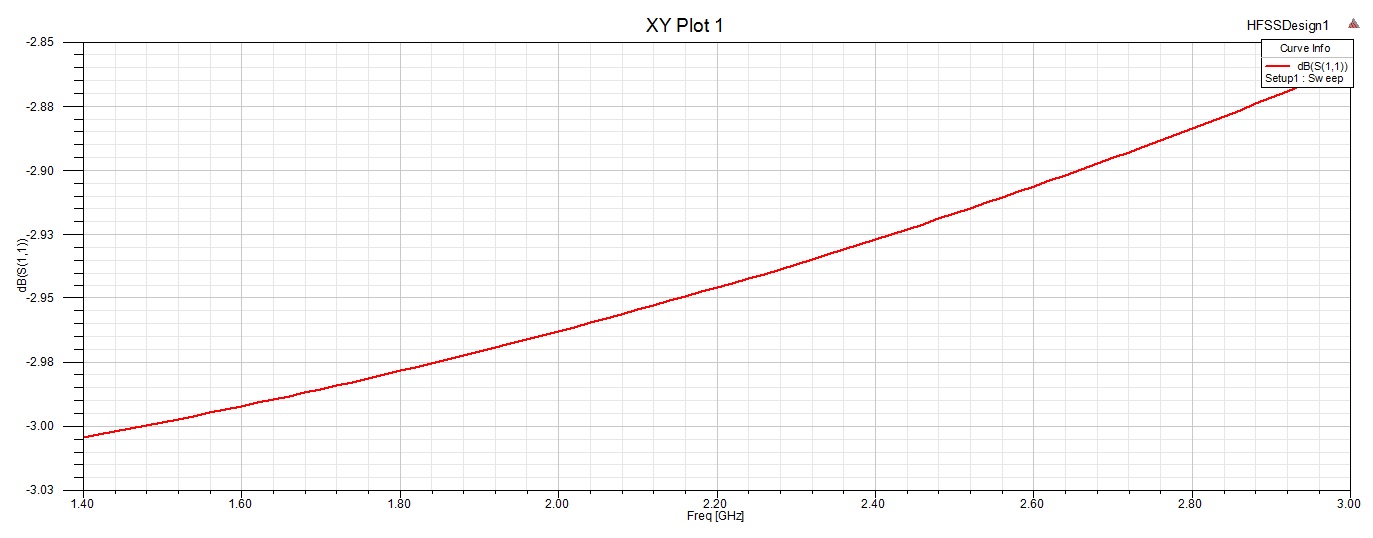
But this is what i got

Thanks!
Hello neffi,
Select the circular face at the tip of the coax and assign a waveport, the integration line should be from the center core to the metallic shield. For more information look in this user guide:http://anlage.umd.edu/HFSSv10UserGuide.pdf there's an example about probe feed antenna
Thanks for your answer Nour Nachabe, it was really helpful
Now I have to get this
It's the near field plot but I don't know how to get it for each X and Y component
You r welcome, to plot the x and y components you should use the fields calculator (right click on Field overlays to open it), follow these steps to get the X component :1. Select E from quantity
2. Select Phase from function
3. Select AtPhase from complex
4. Select Scalar X from scal
5. Add it and name it
You can then make a surface at the distance you wish to see Ex, right click on the surface, plot fields, named expression and you choose the expression you just defined.
For more information on fields calculator look at : http://lsun.people.ysu.edu/ECEN%2037...okv12_14.5.pdf
Good Luck
Thanks man!
Now my last request is this
Here, like the image says, I have to get the comparison of the cross-polarization levels as obtained from near field to far field transformation of the observation plane (the surface used previously) versus the radiation box for different angles
In fact you can deduce Ecross and Eco from Etheta and Ephi, u can find the equations by following this link [URL="http://cp.literature.agilent.com/litweb/pdf/ads2008/emds/ads2008/Radiation_Patterns_and_Antenna_Characteristics.htm l#RadiationPatternsandAntennaCharacteristics-1105213"]
Take alpha = 0 and simulate those expressions in HFSS, to do so
Create far field rectangular report
Make a new expression by clicking output variables
Write your expression using the variable Phi and save it under the name crosspolarization (In your figures there's the cross and the copolarization levels)
And apply the trace
Doing so u will have the cross for far field, for near field I suggest that u make a near field sphere by right clicking on radiation and then you follow the same steps but for near field.
For different phi you have to change the parameters of the infinite sphere, in your case start 0 stop 135 and step 45
rectangular Port patch 相关文章:
