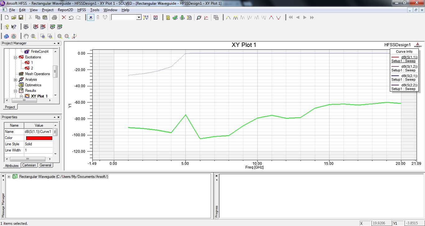
[HFSS 13] Rectangular Waveguide wrong Sparameters.
I take my results wrong. Parameter S1 1 should be 0 db as we are talking about the Reflection coefficient from port 1...
Am i missing something?
Finite conductivity to 4 surfaces, 2 ports for my wave. Vacuum inside.
Any clues?
Rectangular Waveguide.rar

Thanks in advance.
Try out the examples that come with HFSS theres a magic T one that uses waveguides and will show you how to set up your waveguide.
I have already checked it, i have seen many tutorials on youtube , i checked hfss help and i follow the steps coreclty. though it s still wrong.
S11 is reflected power, not the same as the reflection coefficient. S11 of 0 dB would be total reflection. Remember that dB is a relative power calculation. Your plot is correct for the expected performance of a waveguide. the 3dB cutoff frequency is close to 5 GHz as calculated.
could you specify on the graph which belongs to S11,S21 and so forth. thanks.
Yes sure. S11 and S22 are the graphs which start at -90 db and S12 and S21 are the graphs which start at -28 db then goes 0.
they are all the one over the other.
reidintransit S11 is the reflection coefficient of the "entrance" and is equal to V1r/V1i (reflected voltage wave in entrance 11 / incident voltage wave which enters entrance 11)... with a little search i found that 0 db is full reflected power, so maybe you are right. I should ask my professor because i think he told me S11 should be 0db , but this sounds wrong. Thank for the replies guys. I will update soon.
Even I'm also getting same graph for WR-90 waveguide. Before cut off also waveguide is functioning.
what is the reason ?
Regarding the graphs in this post , they are correct. And waveguide should function before cut off, what do you mean?
from graph plot, waveguide is working from 1-20 Ghz ( from return loss plot). But it should start working only after cutoff frequency ( like 6.56 Ghz for WR90) and Waveguides have narrow BW but in plot it is showing nearly 20Gz bandwidth.
So what is it indicating ?
In my case I simulated WR90 waveguide. it should work only from 8.2 -12.5 Gz but from S11 plot, I observed 1 - 30 Ghz return loss is around -30 dB.
So how to analyze Waveguides from HFSS S11 plot?
Yes and no. Every S11 calculation needs a reference impedance Z0 for calculation. For this waveguide port, the reference Z0 is NOT a fixed resistance. It is the impedance of the waveguide at the wave port. And because the DUT is the exact same waveguide, there is zero reflection.
This does NOT mean that the mode can propagate. S11=0 only means that the input impedance is the same for device under test and reference.
ok. Thank you. So here S11 is giving matching/reflection coefficient information not return loss.
we usually find BW from return loss plot i.e. S11. But here this case will not work.
I want see BW of waveguide from HFSS. Then how check n from which plot ?
I would beg to differ with volker, if I am understanding his statement correctly.
S11 is the return loss, it measures the real power that returns to the port when real power is input into the system from the port. If a lossless waveguide is under cutoff, S11 will be unity (0dB), even when it is matched properly.
HOWEVER, in HFSS, the waveport below cutoff knows that it is exciting an evanescent mode, such that it won't carry any real power. According to the above definition, since there's no real power reflected back, the return loss is extremely low (S11 < -50dB). Thus, in HFSS, the return loss is low both a low and high frequencies, with a sharp peak of approximately unity around the cutoff frequency.
This result in NOT physical, since any measurement you take will involve the transmission of real power and hence a HIGH return loss (S11 around 0 dB) below cutoff.
There are different ways to look at S-parameters. But in any case, they always need some reference impedance/reference line. And if the reference and DUT are the same, there is no reflection. That's true even if it is an evanescent mode like waveguide under cutoff.
That's only true if you include something like a coax to waveguide transition, where the reference impedance is fixed (instead of the waveguide itself).
Umm... If Im'm understanding you correctly, you just said that real power incident on a waveguide under cutoff will not reflect (assuming an impedance matching condition)
The evanescent mode does not carry real power... so can you tell us where the power goes?
No, this is not what I said. I only explained why the software shows what it shows.
Rectangular HFSS Sparameters 相关文章:
