Impedance matrix and differential impedance
时间:03-31
整理:3721RD
点击:
I'm using trace analyzer to calculate differential (and single ended) impedances for PCB design. Otherwise everything works fairly agreeably, but for some reason TA insists on giving broadside coupled impedance in matrix form.
I know this is very basic mathematical stuff but I was always much better designer than mathematician and I've been always weak on notation and symbolic manipulation..
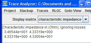
Based on Bogatin's Sigint book I think the notation stands for
Z11 Z12
Z21 Z22
Odd mode impedances would be determined from Z11 - Z12 and Z22 -Z21, right? So Differential impedance would be
Zdiff = 34,7 - 4,3 + 43 - 4,3 ~= 69 ohm
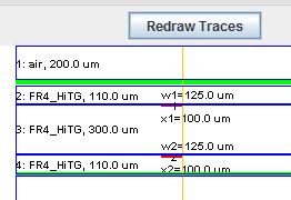
There's a slight discrepancy between Z11 and Z22 as one of the trace layers are defined sitting on top of the prepreg, the other is defined as sitting inside it..
---------- Post added at 17:05 ---------- Previous post was at 17:01 ----------
Here are the missing links, can't use links on your 1st post..
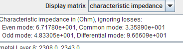
So for normal edge-coupled traces I get this:
However for broadside coupled traces
I get a matrix instead:
I know this is very basic mathematical stuff but I was always much better designer than mathematician and I've been always weak on notation and symbolic manipulation..
Based on Bogatin's Sigint book I think the notation stands for
Z11 Z12
Z21 Z22
Odd mode impedances would be determined from Z11 - Z12 and Z22 -Z21, right? So Differential impedance would be
Zdiff = 34,7 - 4,3 + 43 - 4,3 ~= 69 ohm
There's a slight discrepancy between Z11 and Z22 as one of the trace layers are defined sitting on top of the prepreg, the other is defined as sitting inside it..
---------- Post added at 17:05 ---------- Previous post was at 17:01 ----------
Here are the missing links, can't use links on your 1st post..
So for normal edge-coupled traces I get this:
However for broadside coupled traces
I get a matrix instead: