Slot antenna using HFSS
I recently started doing simulations with HFSS, still pretty newbie, so I'll be needing some helps from you experts..:D
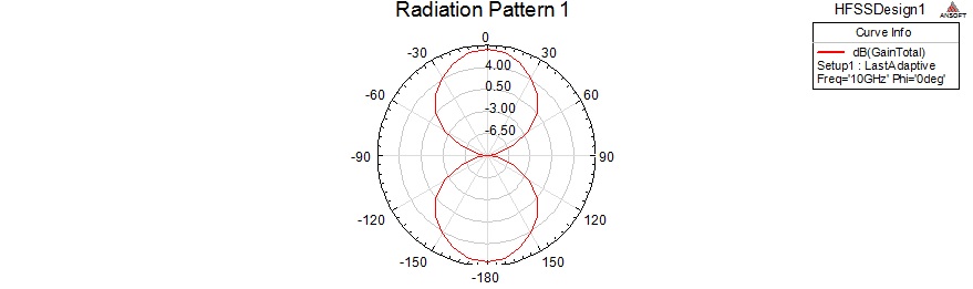
I was trying to make a 10 GHz slot antenna. Its slot is half-wavelength long and I used lumped port for it.
But the radiation pattern that I got from it is not like that of a half-wavelength dipole like it should be (isn't it?).
I attached the design here, will be waiting for helps from you experts,,
Thanks.
hi
i think your simulation is wrong and i cant understand your idea
Hi,
You may use Antenna Design Kit, It would help you to draw slot antenna. Kindly refer https://www.edaboard.com/entry481.html.
Hope this helps
Crazyprof,
I ran what you posted, and this is what I got
Cesar
I'd like to, but sadly I'm using HFSS v.11 in my Uni computer.
Thanks nonetheless.
hi
what u need ?slot microstrip or slot antenna ?
But the 3D radiation pattern didn't show the donut-like pattern that a halfwavelength dipole has.

I thought both the halfwave length dipole and halfwave length slot antenna should have the same radiation pattern.
Slot Antenna, I attached the design on the first post. Can you help me?
hi
your simulation is not true.
1- where is your wave guide
2-u should design the probe for excitation in waveguide
3-where is your sweep
I'm trying not to make it in a waveguide, it's supposed to look like this : http://www.ctr.at/carinthian_tech_re...itzantenne.jpg
Crazyprof,
You are simulating a slot half wave dipole, which is the complementary to a half wave dipole. You should expect to see, in the radiation pattern, everything but what is seen in a half wave dipole. When you add the two radiation patterns you should get very close to a full sphere. What you have works perfectly for a half wave SLOT antenna, not a half wave dipole. You can look at this link for a very brief description. Basic Slot Antenna and Its Complementary Dipole. I also attached your simulations with an added dipole simulation.
Cesar
Sorry for the late reply,
from that link that you gave me, it is said that electric lines in dipole is the magnetic lines in slot, and the also the other way around, but it is not said about how the radiation pattern should be.
It should have form like the one from dipole, just the direction is different.
Because it is said that the slot should be cut into an infinitely large metal sheet, It came to my mind to use "infinite ground plane" on the perfect E boundary.
In the end I got the donut pattern like that of the dipole, but just the half of it.
It seems because the background doesn't cover the part below the sheet, but if I am to use infinite ground plane, the background has to fully touch the infinite perfect E.
I attached the design again, can you help me with it? Thanks a lot.
The air box needs to be extended in the negative z-direction if you want to see what the pattern is going to like there.
Cesar
If I did that, there will be a warning saying that the background does not fully touch the perfect E boundary, this could produce incorrect result. And yeah, what I get is something I don't recognize.
Crazyprof,
I am not sure about the error. I am running HFSS 13, and I do not receive that error. I looked at you sim again and I think I know why you are not seeing exactly what you want to see. It is a scaling issue; I have never liked how HFSS auto scales thing. When you plot the pattern use gain->gainTotal->db10normalize.
Cesar