Simulation of Coplanar Waveguide in HFSS.
I have simulated coplanar waveguide (ungrounded) in HFSS and defined waveport as excitation source with waveport width 3* (2g +W) and height of port 4*h and defined integration line from sideground to trace. However I am not getting proper E field distribution the field is scattered throughout the substrate. can anybody give clue what went wrong?.
Thanks
The integration line is not very important. The size of your port is not large enough.
here is the port field display:

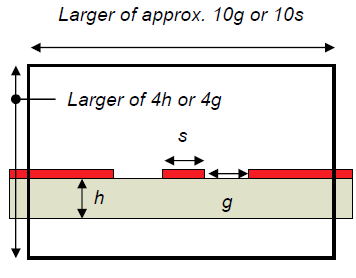
CPW Port Guidelines:
Assume that the slot width is g, dielectric height is h, Assume center strip width is s.
Port Height should be at least 4h, or 4g (larger). Remember to include air below the substrate as well as above!
If ground plane is present, port should terminate at ground plane.
Port Width should contain 3-5g or3-5s of the side grounds, whichever is larger (Total about 10g or 10s)
Port outline must intersect side grounds, or they will ?float? and become additional signal conductors along with the center strip.
Hi
thanks for the info.however one more doubt I have given boundary condition as finite conductivity to the trace and perfect E to the sidegrounds is it okay?.Also the S11obtained from the solution data is negative for some frequencies in the sweep why so ? Why is port Zo calculated different from calculated Zo from the physical parameters of the CPW( checked with several on line impedance calculators).
thanks .
Hi
I have few more queries on the topic
1. What are the boundary conditions to be side grounds and trace are they be given perfect E to all of them or finite conductivity to trace and perfect E to side grounds. what should be the width of side grounds.
2. When the air box is given radiation boundary it touches the perfect E of the side ground. HFSS gives message that radiation boundary overlap with perfect E is it okay.
3.The port Zo calculated by HFSS is different from that calculated from impedance calculators available online why so?
Can someone help
Thanks
Coplanar Simulation HFSS 相关文章: