Coplanar waveguide - S parameters curves characteristics - HFSS
时间:03-29
整理:3721RD
点击:
Hi Edaboard,
I am at the moment simulating a coplanar waveguide of 1 mm length using HFSS.
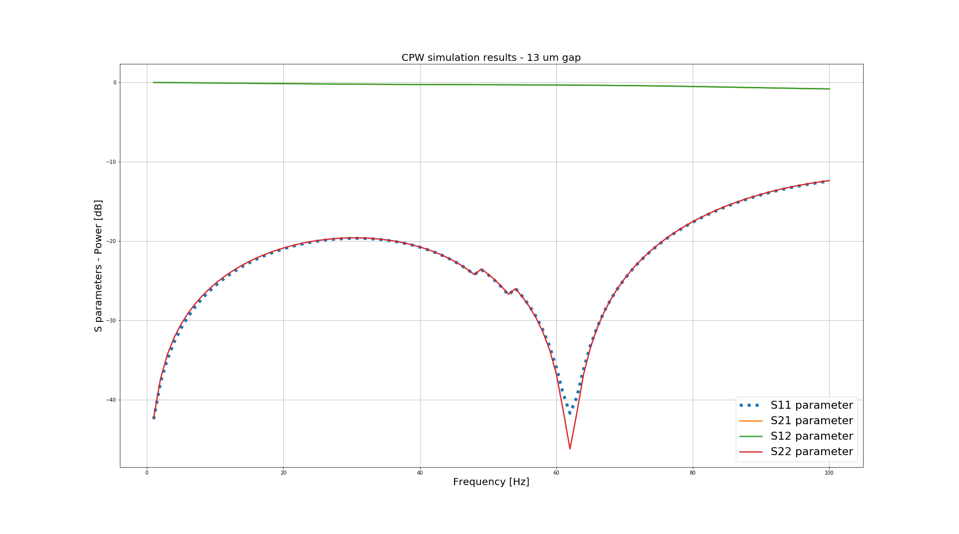
Following you can observe a graph showing the computed S11 and S21 parameters from my structure:
As can be observed, for the S11 curve there is a type of "resonance" at a frequency close to 60 GHz
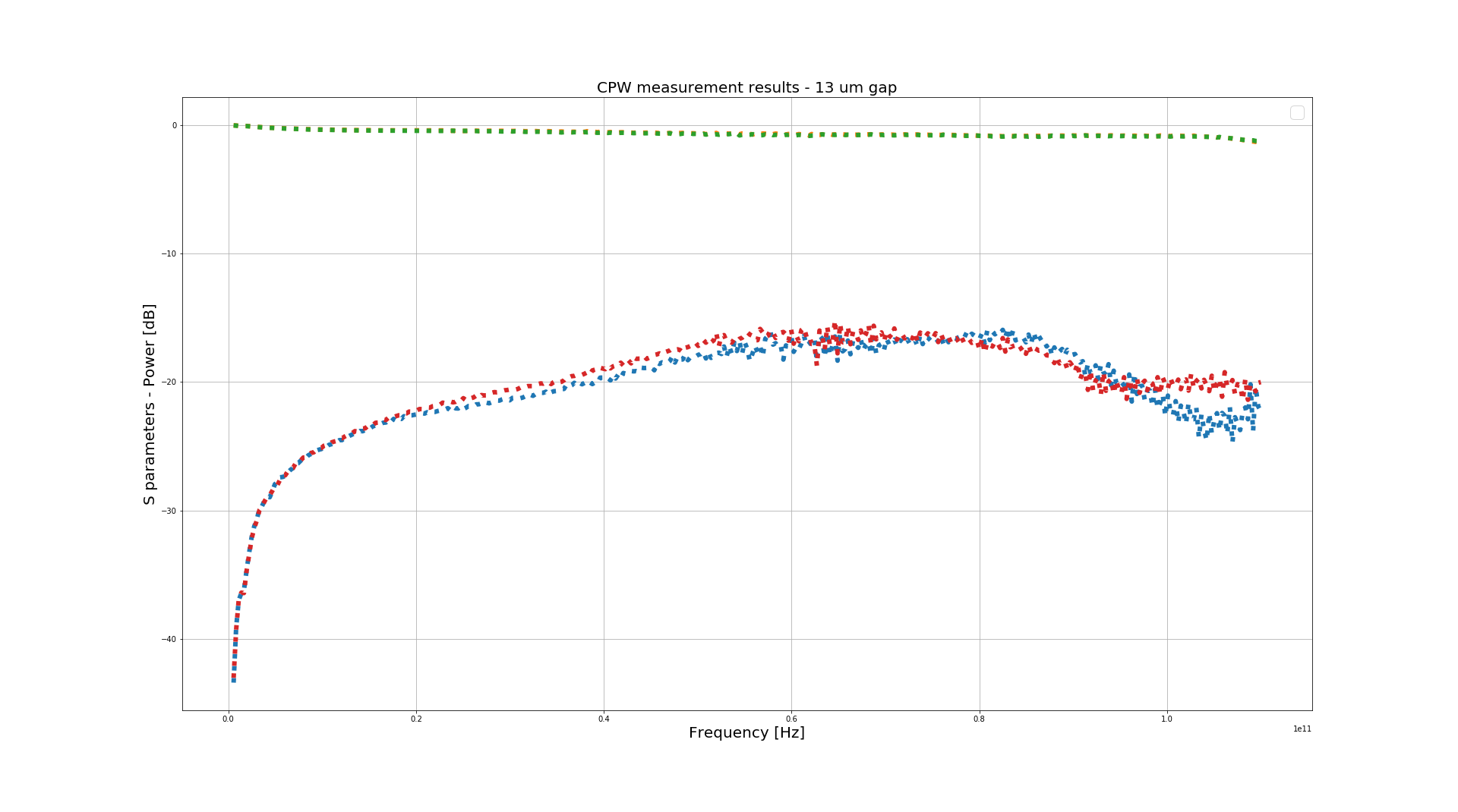
Unfortunately, this type of feature is not observed in the curve corresponding to a real device(same dimensions) measurement as shown below:
What could be the reason for this difference in the curves characteristics? I have tried changing different things in my simulation scheme in order to get rid of the "resonance" peak shown in the S11 curve (replacing the conductors for PEC, extending the excitation ports, extending the total computational volume) but I have not been able to get rid of this feature.
For reference, you can take a look at my excitation scheme (using wave ports with port fingers) through the following image:
Could this "peak" in the S11 curve be due to a resonance in the structure? Or could it be related to the finite height of the excitation port? (The location of this peak also changes as a function of the wave port height)
Could it be that it couples portion of the reflected field from the structure to a non propagating mode or evanescent mode induced by the type of wave port excitation?
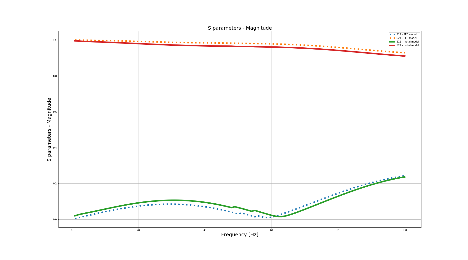
You can take a look at the magnitude of the S11 and S21 parameters (using PEC for the waveguide's electrodes and using the original gold electrodes) through the following graph:
You can observe that at around 60 GHz, the magnitued of the S11 parameter decreases and then rises once again; in accordance with the observed "resonance peak" in the S11 parameter curve given in dB units
Any comment or suggestion on what could I do in order to have consistency between the simulation and the lab results would be highly appreciated.
I am at the moment simulating a coplanar waveguide of 1 mm length using HFSS.
Following you can observe a graph showing the computed S11 and S21 parameters from my structure:

As can be observed, for the S11 curve there is a type of "resonance" at a frequency close to 60 GHz
Unfortunately, this type of feature is not observed in the curve corresponding to a real device(same dimensions) measurement as shown below:

What could be the reason for this difference in the curves characteristics? I have tried changing different things in my simulation scheme in order to get rid of the "resonance" peak shown in the S11 curve (replacing the conductors for PEC, extending the excitation ports, extending the total computational volume) but I have not been able to get rid of this feature.
For reference, you can take a look at my excitation scheme (using wave ports with port fingers) through the following image:

Could this "peak" in the S11 curve be due to a resonance in the structure? Or could it be related to the finite height of the excitation port? (The location of this peak also changes as a function of the wave port height)
Could it be that it couples portion of the reflected field from the structure to a non propagating mode or evanescent mode induced by the type of wave port excitation?
You can take a look at the magnitude of the S11 and S21 parameters (using PEC for the waveguide's electrodes and using the original gold electrodes) through the following graph:

You can observe that at around 60 GHz, the magnitued of the S11 parameter decreases and then rises once again; in accordance with the observed "resonance peak" in the S11 parameter curve given in dB units
Any comment or suggestion on what could I do in order to have consistency between the simulation and the lab results would be highly appreciated.
Your "resonance" is where S11=0 in simulation. Simulation is rather ideal here, and very simple.
In measurement, you have multiple small reflections in coax-to-waveguide transition etc, so that you don't get down in S11 as clearly as the simple simulation model.
