Time Domain Reflectometer
Iam in middle of a project which impliments to measure of find fault locations in an underground cable. i think using the principle of Time domain reflectometry(TDR) the problem can be solved. Anyone have the idea about how to implement the TDR using a microcontroller (PIC or AVR)?
i stucked in that how to implement it
I presume, that a microcontroller can play a useful role in the overall instrument design. The TDR specific measurement circuit works in a timescale (ns to μs) where a microcontroller can't directly take part.
Have you already fixed your specification about measurement range, resolution and accuracy?
thank you FvM... actually i want to design a prototype to measure the cable fault in the length less than 1KM. the resolution may be 0.5 feet that is enough for this application.. i found a note by microchip in this era. bt they said that the maximum length is <200feet
You are referring to AN1375 and the therein quoted ECN articel Low-Cost, High-Resolution Time-Measurement Application | ECN: Electronic Component News
Microchip utiizes analog time-to-voltage conversion to extend the timing measurement capabilties of the microcontroller. According to the article, PIC24 CTMU achieves about 1 ns resolution with the 10-Bit ADC. The 200 feet limitation is simply set by the 10-Bit CTMU range. It could be overcome by designing more complex digital logic, delaying the CTMU start pulse relative to the TDR send pulse.
is it possible to design a lowcost TDR? iam doubtful because the resorce available in the google is very low, and nobody build a lowcost proto at all... I thnk there are much more complexity to design such a device with the microcontroller.. and also i found a note of TDR which implemented using FPGA..
I think, for limited performance requirements, the μP design idea is a reasonable way. You should have some kind of reference cable for your project.
you want to generate a step in voltage to send down the transmission line. You want a very fast rise time. Can probably use a micro to drive a very fast logic gate to do that.
Then you need to sample the return reflections to find the meausred cable faults some time later. A simple analog to digital converter is probably not going to be fast enough to actually measure the return pulses (you would probably need something like a 5 GHz sample rate on the ADC). So you should use something called "equivalent time sampling", some sort of track and hold or sample and hold circuit, and then a slow speed adc.
I guess, you didn't review the previously mentioned Microchip application. It's said to achieve 1 ns TDR resolution. That's not mind-blowing, but apparently sufficient for the project. The application also suggests a pulse driver circuit.
I did. I just did not believe it! Where is this switch with the magical 1 ns switching time described? No part number, no schematic.
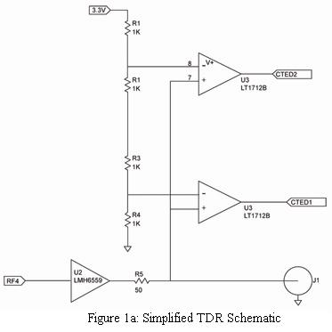
The article gives the below schematic. I would comment, that you don't need an expensive high speed analog buffer and better use fast logic gates to drive the cable.
The key point is, that you don't need 1 ns rise time to measure cable length or the location of a massive fault with 1ns resolution. It can work with 5 or even 10 ns rise time as well. Rise time and also time resolution of the receiver comes into play, if you want to display TDR details, which obviously isn't the objective of the application.
You're right to mention that it's limited compared with a full featured TDR instrument. To learn about TDR measurement, I would generally suggest to use a standard fast laboratory pulse generator and a fast oscilloscope. The setup can be also used to validate the results of a simplified design as the suggested Microchip one.
In my opinion, it's the PIC24F CTMU is an interesting feature, although some unrealistic expectations are addressed in the application note, e.g. ultrasonic doppler measurement, that in fact needs picosecond time resolution to design a state-of-the-art flow meter.

I am replicating the schematic given in the mentioned article and implementing a TDR based application. As I understand the comparators in the circuit are used to trigger the EDGE2 of the CTMU by the reflected wave, can anyone explain the above schematic in little more details?
I think, the circuit operation is obvious from the description in the ECN article. EDGE1 is expected to trigger on the forward wave edge and EDGE2 on the reflected.
From the article-
It's quite ambiguous, since CTED1 and CTED2 are the pins but EDGE1 and EDGE2 are the channels on both pins.
The good point with the ECN article is that the author apparently implemented a real hardware circuit according to the shown waveforms. The article doesn't discuss the CTMU programming details, maybe he thought they are obvious.
Time Domain Reflectometer 相关文章:
