Normalize to fixed impedance 50 Ohm. CST
What is the differencec with or without it?
thanks a lot
This is related to the Z0 problem in your other post.
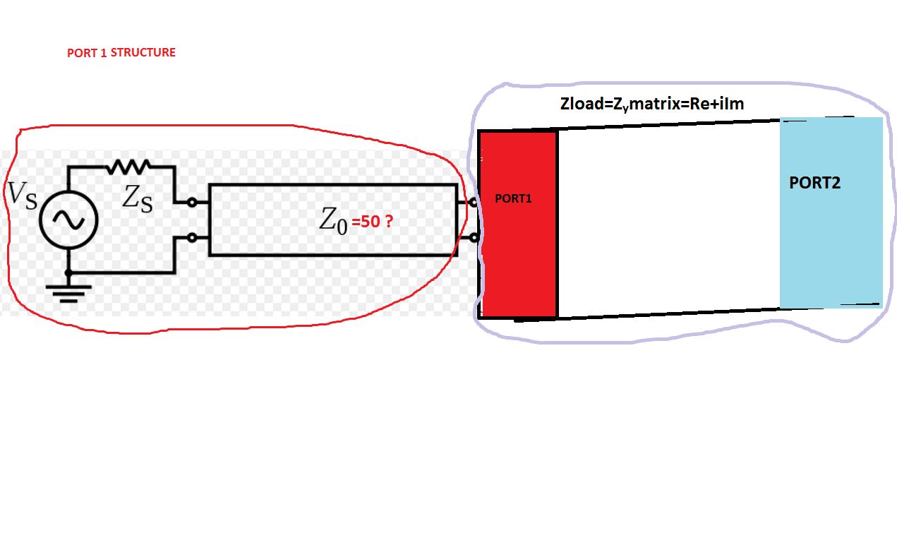
For wave guide ports, some 3D simulators define Z0 as line impedance at the port ("generalized S-parameters"). This means that any straight line will have perfect match, no matter what the dimensions are. However, the simulator does know that Z0 value and can re-normalize the S-parameters to 50 ohm port impedance. This is what the switch does: it allows you to switch between generalized S-parameters and 50 Ohm S-parameters.
I almost understand what you mean my friend, but i need an example.
Icase_Without normalize to 50Ohm, for e=2 and some specific dimensions, a waveguide port gives |s11|=0,40 phase=93degrees and |Zin|=|0.29+i2591|=2591Ohm with phase=89 ,also VSWR=2,31.
IIcase_With normalize to 50Ohm the same one is: |s11|=0,94 with phase=14degrees, and |Zin|=|0.39+i2591|=2591 ohm and phase=89, also VSWR=36,13 .
As we can see the Zin impedance of the waveguide did't change cause i didn't changed any of the materials and the dimensions.
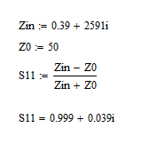
But the S11 changed much and i don't understand it.The formula s11=Zin-Zo/Zin+Z0 for s11,Zin complex numbers
is it right for each case?
Thanks for all i apreciate this
Yes, exactly.
If you now calculate the S11 value for your chosen reference impedance Z0, that S11=(Zin-Z0)/(Zin+Z0) will depend on the value of Z0.
Can you please explain mathematicaly the numbers of s11,phase,Zin and Zo that i have write above?
No, sorry. That's your homework.
hehe it is not that i am boring bro. It is that the numbers with "normalize to 50" ,for |s11|=0,94 with phase=14degrees, and |Zin|=|0.39+i2591|=2591 ohm and phase=89 ARE WRONG. If you take these numbers and search for Zo you will not have 50. That's my question . WHY?
Ok, I see what you mean.
You should contact CST support to find out.
I will go ask my professor at the university...i he don't know i will ask support team! Thanks a lot for all!
Hello,
Between the Z and S matrix the relation is not as simple as you write. You can not write that S11 = (Z11-Zo)/(Z11+Zo). Have a look at a HF book to see the relations. In fact you find that :
Z11 = Zo ((1+S11)(1-S22)+S12*S21)/((1-S11)(1-S22)-S12*S21))
And so on for the others parameters.
ok...so...the exression Z11 where is refering to? I understand at the resistance of the waveguide at the port I, right?!
@eraste: You are correct for Z11, but this is not what we discussed. Zin is the input impedance into port 1 with the other ports terminated.
@Volker. Yes but CST produces Z11,Z21 not Zin :O! The Zin how do we calculated from Cst? All the above at my posts that i have write about Zin are reffering for Z11.
So if the formula of eraste is correct for the determination of Z11 we need not only s11, but s21,s22,s12 !
volker are you running Cst or HFSS or both?
Thanks for the company bro :)
None one them. I use Sonnet (planar) and Empire XCcell (3D FDTD).
The waveguide is seen like "quadrupole" . Between the S matrix (S11 S12 S21 S22) and the Z matrix (Z11 Z12 Z21 Z22) , we have not the relation Z11 = Zo (1+S11)/(1-S11).
Refer at any book deal with filter or scatering parameters. This latest relation is true only for "dipole".
@eraste!can you make any attachment of the notes you have about it?
So for my restrangular waveguide Z11 = Zo ((1+S11)(1-S22)+S12*S21)/((1-S11)(1-S22)-S12*S21))
is ok?>!
Hi,
Have a look at this link : http://www.ece.rutgers.edu/~orfanidi/ewa/ch13.pdf
and read the 13.3 paragraph.
On the web you could find several pdf files about conversions between matrices ABCD Z Y S ...
Thanks so much eraste !