Three phase inverter simulation
I am trying to simulate three phase sine wave inverter in OrCAD PSPICE using sinusoidal PWM. I dont know how to achieve proper output AC volatage value . Switches seem to be driven properly, but output sine waves have magnitude only cca 11 V. i dont know what i am doing wrong. No matter how i change DC input voltage, output doesnt change. thanks for Your help.
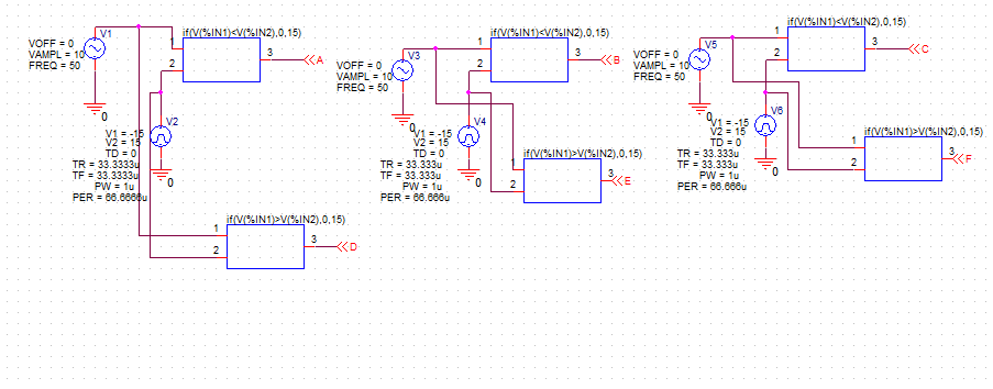
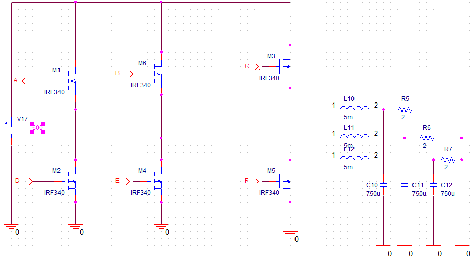

ive attached my schematics and output voltage waveform
I recommend that you put a scope trace on the coils. They are the heart of the action.
The capacitors as well.
I suspect you have dead time, when the bias is insufficient to turn on either mosfet. After the high mosfet has been on, the coil is charged (conducting amps). Then the mosfet turns off. However the coil needs to send that current somewhere. Look for a high voltage spike from the coil.
A popular beginners fault in designing H-bridge drivers.
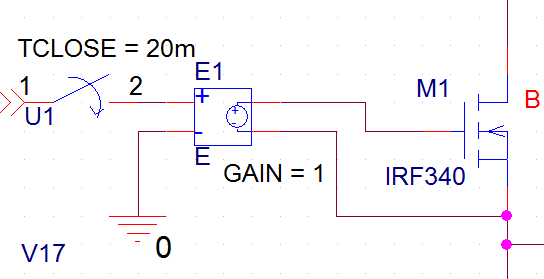
High side driver voltage must be refernced to source of high side MOSFET rather than ground. Use voltage controlled voltage sources as level translators in simulation.
Thanks, applying Your solution worked perfectly. I have another question, how can be AC output modified to start from zero (or cross zero)? (i would like to accomplish three phase power supply)
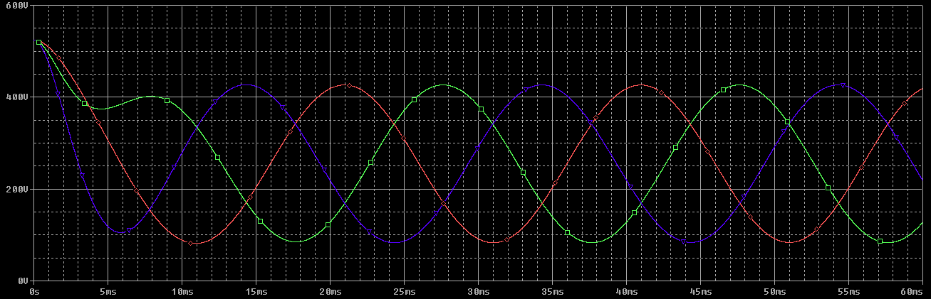
Ive attached output voltage waveform.
The circuit has not starpoint, in so far you can say that the voltage starts from zero.
To start from mid supply, you have to disable all transistors at startup and would precharge the filter.
how exactly can be this done? i tired to disable transistors at startup, but it didnt work
I think, I mentioned the necessary steps.