Phase reference of Etheta in HFSS
时间:03-29
整理:3721RD
点击:
HFSS Phase Reference for rE_theta
In HFSS, I built a half wave dipole and placed the radiation box at lambda/4 from the dipole edges. From far field reports, I created the radiation pattern for the Real and Imaginary rEθ.
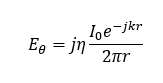
Theoretically, at Φ=0° and θ=90°, Eθ is given by:
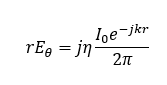
so rEθ should be:
I understand that the magnitude of the rEθ does not change with r. However, the angle between the real and imaginary parts depends on r:
My question is at which r does HFSS calculate rE?
As an example, consider a half-wave dipole with lambda =51.7 mm located at origin and oriented in the z-axis. The radiation box extends from -13.13 mm to 13.13 mm in both x and y directions. When I plot rEθ pattern, at Φ=0° and θ=90°, I get Re[rEθ] =-5.2 and Im[rEθ]=-7.2. That is, the angle between them is -2.2 rad. This angle should actually be π/2 -kr. With k=2π/lambda, r becomes 30.1 mm. That is, HFSS calculated the real and imaginary components of rEθ at 30.1mm from the origin. Any reason for this specific r?
In HFSS, I built a half wave dipole and placed the radiation box at lambda/4 from the dipole edges. From far field reports, I created the radiation pattern for the Real and Imaginary rEθ.
Theoretically, at Φ=0° and θ=90°, Eθ is given by:
so rEθ should be:
I understand that the magnitude of the rEθ does not change with r. However, the angle between the real and imaginary parts depends on r:

My question is at which r does HFSS calculate rE?
As an example, consider a half-wave dipole with lambda =51.7 mm located at origin and oriented in the z-axis. The radiation box extends from -13.13 mm to 13.13 mm in both x and y directions. When I plot rEθ pattern, at Φ=0° and θ=90°, I get Re[rEθ] =-5.2 and Im[rEθ]=-7.2. That is, the angle between them is -2.2 rad. This angle should actually be π/2 -kr. With k=2π/lambda, r becomes 30.1 mm. That is, HFSS calculated the real and imaginary components of rEθ at 30.1mm from the origin. Any reason for this specific r?