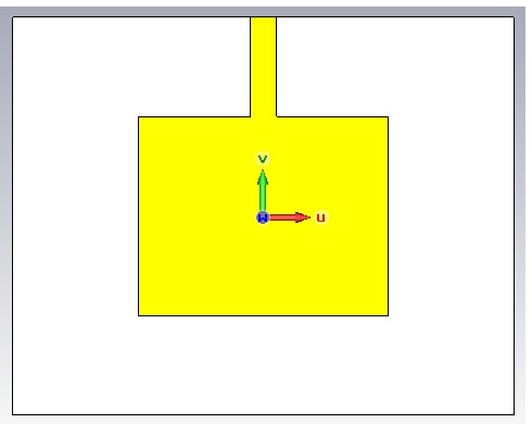
how to know return loss right or wrong
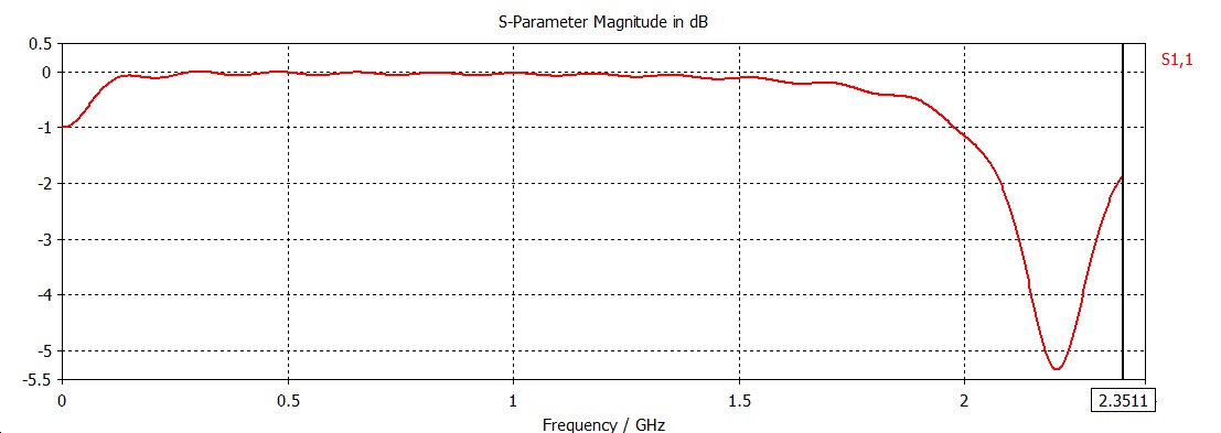
F=2.35 and return loss attached
Attachment 103678Attachment 103679


Return loss is 10*Log10(incidentPower/reflectedPower). So S11 should contain all these information, just in different format of description. To my knowledge, there is no analytical formula to calculate return loss over frequency, unless your geometry is in extreme case, such as 0 thickness thin wire, or 0 thickness patch without considering the feeding structure. You can predict the resonant frequency analytically in such case.
As for the loss, if the metal is PEC and substrate is lossless, then the loss is 100% caused by the mismatch. However, in practical situation, metal has conductive loss, substrate has loss tangent, these will be mixed with the mismatch and being reflected all together in S11.
Lastly, the feeding will cause additional tricks, it will disturb the mismatch curve and it will has impact on loss as well, such as SMV. CPW, waveguide etc.
So in summary, I would not try to calculate this exactly, roughly we can estimate the general resonate frequency of such size and shaped geometry using simplified models, then allow 10% offset of the frequency shifting due the the thickness and other factors. and 10% offset for loss dB due to real materials, feedings etc. This will tell us if the simulation is in general matching the theory, then compare the simulation with measurement for adjustment of design.
thanks for your help ...... in my simulation what is the problem u think ? I flow online tutorial for design, Patch and transmission line materials are different (FR4 and Copper) ! is that ok ?
http://obrazki.elektroda.pl/7781854500_1396030864.jpg
I do not have your geometry size, so I can not predict the general resonant frequency range. In your S11, it seems it radiating around 2.25GHz but the dB is not low enough.
my frequency 2.35 and I did decrease the dB and that what i get ....thanks for your help
http://obrazki.elektroda.pl/1589197800_1396332778.jpg
