the return loss in the simulation of AMC unit cell
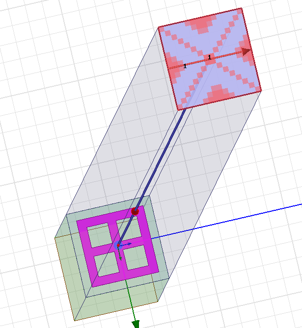
I am simulating an on-chip 77GHz Artificial magnetic conductor(AMC) structure. When I simulated the AMC unit cell in HFSS, I got the rigth in-phase frequency but the return loss S11 is around -10dB which means only few waves are reflected by AMC. Do you have any idea to increase the S11 to near 0dB?


Can anyone helps me? Thanks in advance!
Do you have the S-parameters of the contra-polarized free space mode? Perhaps the power is being scattered into this polarization.
Also, in your figure, there appears to be a conductor backing. I can't tell if your cell has one.
Thank you for your reply!
The substrate is not a conductor. It's a semiconductor. Because I'm designing an on-chip AMC structure, so the substrate is lossy Silicon. Do you have any idea to improve the S11
By "conductor backing" I meant a solid conductive layer on the opposite side of the substrate from the main "cross" pattern. This would definitely help with reflection.
Otherwise, for a lossy substrate, I don't know if you're going to get much better than what you already have.
Oh, I've put a "conductor backing" at the backside of the substrate. Really? Do you think this could be the best result for a lossy substrate? Actually, I've reviewed many papers about on-chip AMC, but all of them don't show the S11 of the AMC unit cell.
In the absence of losses (which is usually a poor assumption at 77 GHz), all of the power should be reflecting (|S11| = 1) if there's a conductor backing. So either the power is being absorbed by the cell, or it's reflecting back in a polarization you're not observing.
loss return simulation 相关文章:
- Return loss and phase graph how to interpret
- Is core loss in an inductor proportional to it's inductance value?
- Computing metallic losses for coplanar waveguide | HFSS
- how can I calculate the returnloss theoritically depending on the simulation results
- Core loss, proximity and skin loss
- How big is core losses in an inductor at 40kHz?