Return Loss Measurement System
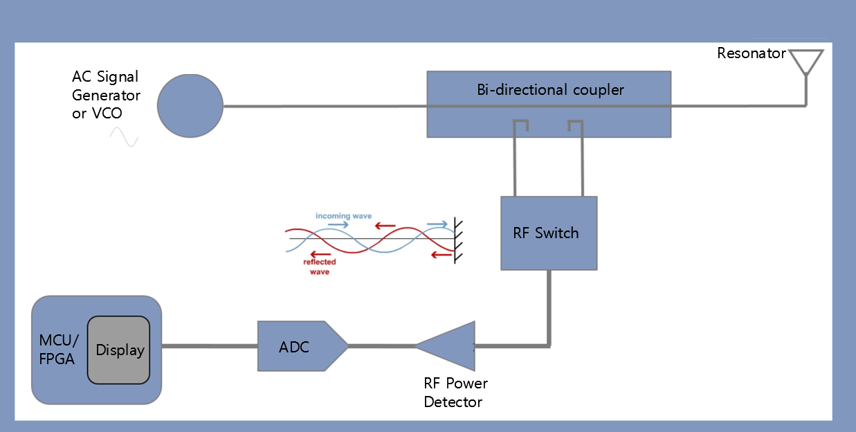
I want to design a return loss measurement system. I will connect an RF resonator and measure its return loss. The block diagram for such measurement setup is attached with this post.
I also want to use the chip (directional coupler and VCO) to miniaturize the size of RF measurement system.
For design such setup, which computer simulation tool do you recommend? And, for the MCU/FPGA part, is it possible to have an LCD display right on the board showing the return loss for every single frequency?
I am not an expert in circuit designing and microprocessor. I am an electromagnetic guy, so the RF resonator part is my major contribution to this project, but again, I also want to design this system.
I will be grateful if anyone can give me the direction and advise of how to start working on it.
Thank you!
Please see the return loss measurement block diagram.

The reonant frequency of the RF resonator is 4.5 GHz
If I were you, I would use 2 Detector+ADC block instead of a single with a switch.In this case, incoming and reflected waves can be observed simultaneously.
Because this system will need a calibration routine along the frequency band of interest due to small deviation of the frequency response of the components.If this calibration is done for -let's say- incoming wave measurements, reflected wave measurements will be erroneously due the difference between reflected wave-incoming wave frequency response of the coupler.
This will be very obvious when the resonator impedance is close to system's characteristic impedance because reflected wave magnitude will be so low and calibration will not be valid anymore.
MatLab can be used for system simulations if the proper model of the detector can be found.ADS and Systemvu can also be used if appropriate models are obtained.
Thanks for your reply.
I am thinking of designing the system in ADS software.
Usually, some companies have s-parameter information available on their websites too.
So, in the case of using two detectors, we do not need a switch, we can just directly connect RF detectors from the outputs of the directional coupler to observe both, reflected wave and coupled wave. Am i right? If I am correct, it seems better approach. We can get two measurements, converting both powers into dBm and then by calculating the difference, we can get return loss value. Am I right?
Yes, you're right.I repeat again here that the calibration is the key point here and it should be done very carefully against all conditions such as temperature and components' specs. variations.
Thanks for your suggestion. Can you suggest any calibration technique for eliminating errors from this system? I will not use coaxial components, I will be using SMT packages of directional coupler and VCO and RF Power Detectors.
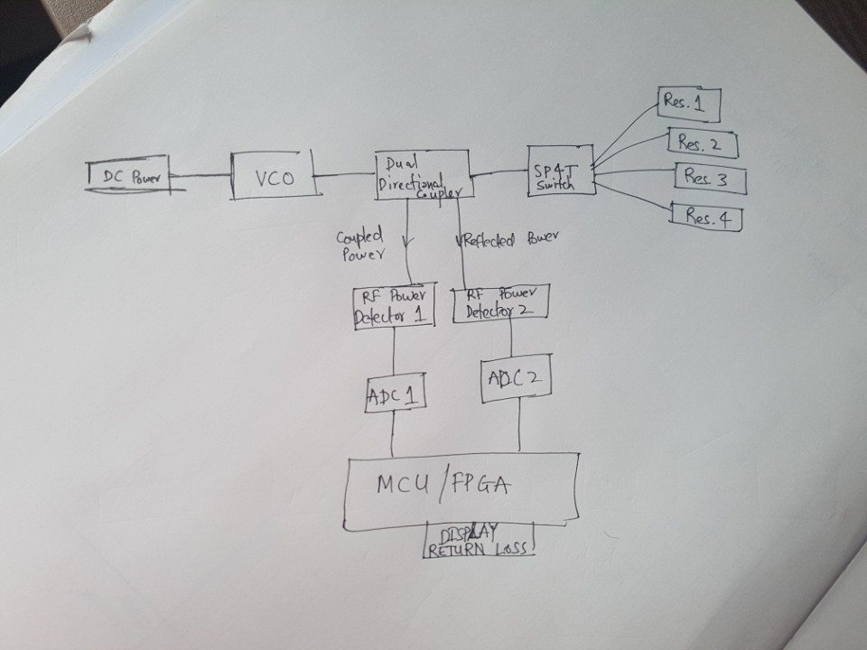
And one more thing, there will be four resonators connected. An SP4T switch will be used at the directional coupler and at a time one resonator will be measured. I am still not sure how can reflect power be passed from the SP4T switch back to the directional coupler. Please see the attached diagram I just drew.
Will it be okay to use an SP4T switch here?

What is the sensors change in return loss that you want to measure? Is it strong shift in resonance frequency or a small change in magnitude?
The four resonators used are of same dimensions, hence the same resonant frequency, impedance matching has already been done too. These four resonators will have microfluidic channels and every resonator will contain a different liquid chemical (a different resonant frequency). And this measurement system will measure two powers (reflected and coupled) and calculate return-loss for each resonator and display it on screen. Another equation in MCU will be used to extract relative permittivity of that chemical (from return loss value and frequency) and directly display it. I am also planning to use data of other 3 resonators as a calibration technique to remove system errors. So, this entire RF sensor module is a permittivity detection system for liquid chemicals.
My question was to find out what precision in reflection (S11) measurement you need. As you might know, for higher precision even the laboratory-grade network analyzers are calibrated ("network analyzer calibration") frequently to obtain accurate reflection measurements. That calibration however requires a complex (vector) measurement, not just scalar (magnitude) as you have designed it.
From what I understand with the liquids, this will tune the resonator to a different frequency, so the effective resonance frequency changes. If you want to measure that change in an S11 sweep over frequency, and the effect is strong enough, then a scalar (magnitude) measurement should be fine. If you need to evaluate absolute changes in magnitude, and not just a resonance shift, then you might need higher precision -> calibration -> vector network analyzer.
Yes, You are right. For now the resonator's frequency will be shifted. Ofcourse the shift is strong enough to be detected. That is the reason I want to make a low-cost miniaturized scalar NA.
It is principally OK but there will be another reflected wave between directional coupler and the switch and this must be eliminated as much as possible for the health of the measurement.
Otherwise it won't be impossible to distinguish where the reflected wave is coming from.There must be ideally zero reflection between the coupler and the switch.In order to eliminate this issue, a pre-calibration should carefully be done and this data is registered into the system memory being as an offset. In further steps, this off-set may be extracted from real data.
I'm not so sure this technique will work or not but it seems to be logical.
If you're not interested in the phase of the reflected and incident waves, this measurement set-up should principally work.If the phase information is demanded , it's another history and the system will be much more complicated. The phase can be obtained by mixing the signals ( incident and reflected) by themselves and a DC ( theoretically ) level is obtained related to the phase of the wave.But this is more difficult in practice and multilevel calibration has to be done.Using a low cost VNA becomes a more proper way.
I will look for proper chip-components for this system architecture. I might again require your help in reviewing the components, once I start designing in ADS.
Thanks for the valuable suggestions.
I am now working on ADS.
Hello,
Just a question what about the directivity of the coupler? Will that have any influence?
Yes, it will have an influence. It will also influence the return loss of RF power detectors. A 15dB to 20dB of directional coupler directivity is a must here.
Yes, it will have an influence. It will also influence the return loss of RF power detectors. A 15dB to 20dB of directional coupler directivity is a must here.
There is a good news for you..
http://www.analog.com/media/en/techn...ts/ADL5920.pdf
This seems a very nice chip component. The only problem I see here is the directivity of the coupler bridge. It is 10dB around 4.5 GHz. I thought, for accurate return loss measurement, the couplers directivity should be higher than 15dB.
Every beauty has a fault..
Haha right.
I am attaching the components that I will use for making the system. I analyzed the working of the Directional coupler in ADS and it is working fine. Please see the attached components and if everything is okay. I will order the components.
1. VCO http://www.analog.com/en/products/rf...oduct-overview
2. Bi-directional Coupler https://www.minicircuits.com/WebStor...YBD-13-63HP%2B
3. RF Power Detector http://www.analog.com/en/products/rf...oduct-overview
4. ADC http://www.analog.com/en/products/an...s/ad7091r.html
5. SP4T Switch http://www.analog.com/en/products/rf...oduct-overview
6. SPDT Switch (In case of using one Pwr Detector and one ADC) http://www.analog.com/en/products/rf...oduct-overview
I want to order multiple copies of these components if the selection is good. Frequency range is 4.4 GHz to 5 GHz.
The directivity of this directional coupler seems good.
Can you please check and give me your views and comments, please?
Thank you!
Don't stick to single manufacturer..
For switches
http://www.psemi.com/products/rf-switches
For VCO
https://www.synergymwave.com/products/vco/
For Directional Coupler
https://www.anaren.com/catalog/xinge...ional-couplers
And the others..Compare them yourself technically and commercially ( I know cost is not the key anyway ) then decide..
I don't know your resonators bandwidth, but you might need a PLL to control the VCO frequency.
Actually, the tuning range of my resonator will be from 4.3 GHz to 4.8 GHz. For that, I want to use this VCO. https://www.synergymwave.com/product...O425514-10.pdf
Does it still needs a PLL?
Actually, the tuning range of my resonator will be from 4.3 GHz to 4.8 GHz. For that, I want to use this VCO. https://www.synergymwave.com/product...O425514-10.pdf
Does it still needs a PLL?
Return Measurement System 相关文章:
- Return loss and phase graph how to interpret
- how can I calculate the returnloss theoritically depending on the simulation results
- the return loss in the simulation of AMC unit cell
- How to remove effect of antenna from measurement result
- CST measurement error (wrong lenght)
- Re: S11 inductance measurement
