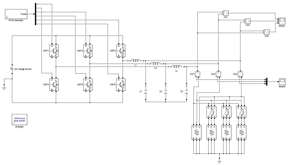
3-phase inverter with different load design by matlab
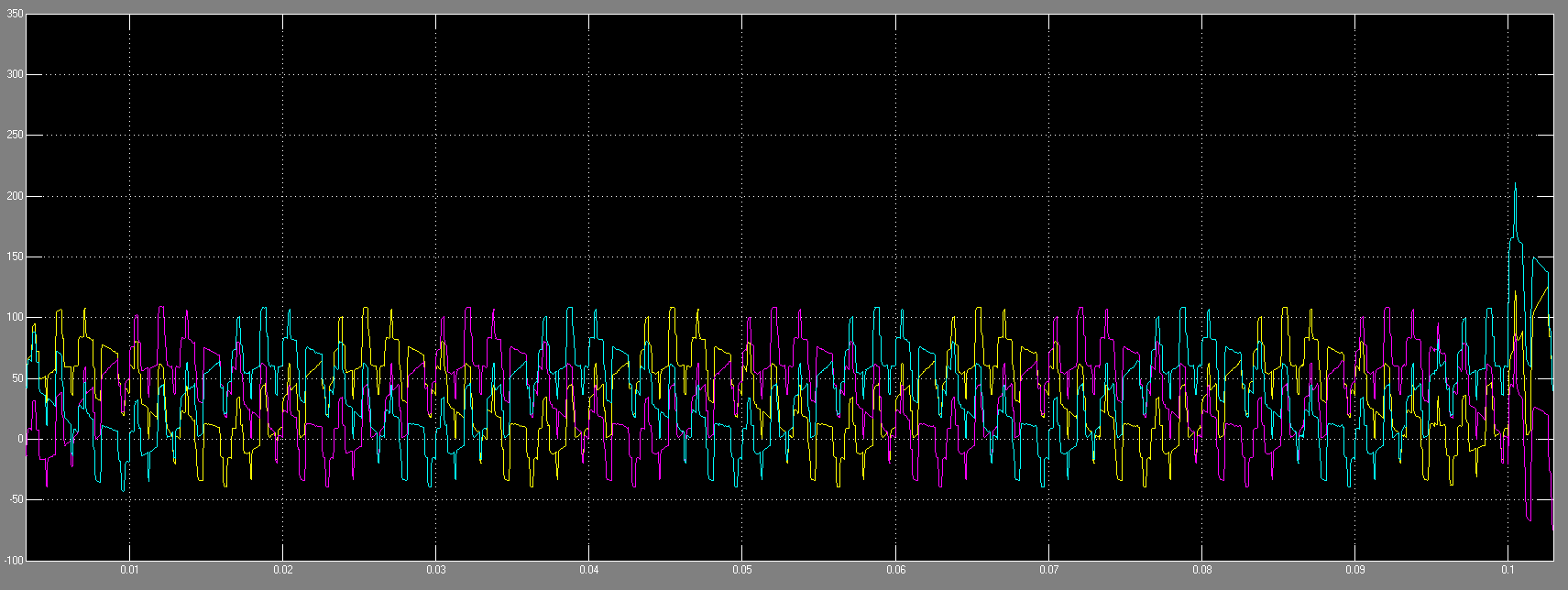
Are you talking about the fact that all the scope traces are shifted toward the positive?
The low peaks appear to be -40 V, and upper peaks 110 V.
I guess you want all waveforms to be centered around 0V?
Hi, Brad, thank your for your replying
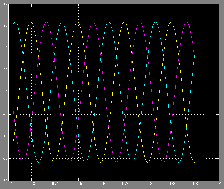
What you have mentioned is one part of my problem, besides, I want the curve to be like the sinusoid(the image shown below but ignore the value).
I have tried to replace the 'resistor' load with the 'resistor parallel with inductor' load, and the schematic looks better, but the value of the current is too big(around 3000A).
I want to figure out the how to choose the component
1.
Three-phase.
Four different loads.
You have a lot going on here.
Did you try a basic schematic of your system? With one phase? One load? Etc.
2.
It would help if you were to provide timing diagrams of your gate-driving waveforms.
3.
It is not clear as to how your LC filters interact. What do you understand to be the path of current through them? Are they supposed to have a connection to ground?
4.
The LC values must be selected to go with your load and operating frequency (or low pass frequency).
The inductor has a reactive impedance. It needs to be calculated so its impedance is in the vicinity of your load.
The same with the capacitor.
The basic inverter topology is correct, except for one important point. You must not ground the bus voltage and the load center point at the same time.
But using a correct topology doesn't ncessarily mean that the control signals and filter parameters are appropriate.
Thank your for your detailed explanation, I have found some of problems:
1. Remove the ground connected to the voltage supply
2. Connect the filter to the ground
3. Increase the value of the inductor of the filter.
and the result becomes better.
Hi, FvM, you are right, and I remove the ground connection to the voltage supply