Modeling layer in RCWA simulation
I've been working with the EMpy simulation software and comparing my results to other suites with good results. However, I'm running into issues modeling layers which are not simple binary gratings.
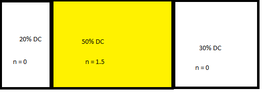
For example I'm trying to get the Fourier transform coefficients of the following layer.
I've been reading all of the papers I can find on the topic but either they are not clicking with me or it has not been discussed.
The library has two functions, one called SymmetricDoubleGrating (I cant get working, or dont undersand) and another Called AsymetricDoubleGrating (I can get working, dont understand). I'd like to understand what exactly is happening in their getEPSFourierCoeffs method given that I believe it's what I'm hopping to achieve.
link to the library and described functions.
https://github.com/lbolla/EMpy/blob/.../EMpy/utils.py
I have a few resources for you. For arbitrary and strange grating cross sections, you can use an FFT to calculate the Fourier coefficients. Take a look at "Lecture x -- FFT" here:
http://emlab.utep.edu/ee4386_5301_CompMethEE.htm
You will need to use many points on your array describing the grating cross section, like maybe 1000 points.
If you are using RCWA and want more details on this method, take a look at Lectures 18 and 21-23 here:
http://emlab.utep.edu/ee5390cem.htm
Hope this helps!
Hi,
Thank you for your previous help! I hope you don't mind me asking a follow up question.
The library I've been studying (EMpy or ElectromagneticPython) uses a Sinc approach to describing binary gratings. I had been wrestling trying to figure out what Sinc was doing in the following code. Should have just googled it earlier! Its the Fourier transform of the rectangle function!
That code is here for reference:
rix1 = 1
rix2 = 1.5
f = .5
h = [-n...0...n]
EPS = (rix1 ** 2 - rix2 ** 2) * f * numpy.sinc(h * f) + rix2 ** 2 * (h == 0)
the sudo code of my workings are as following:
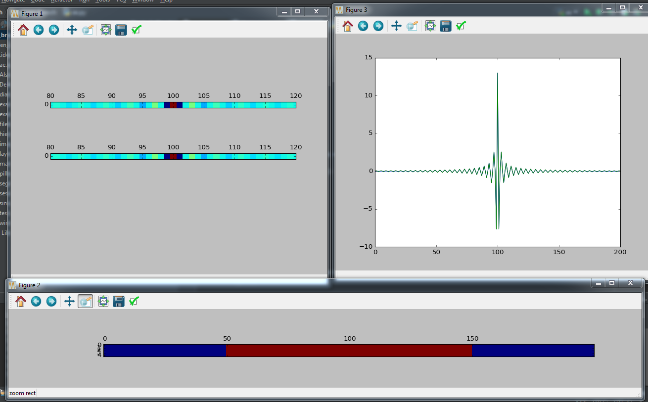
build device on 1xN grid with device centered around midpoint
FFT the device
Thank you!
I have not used this software so this is only my best guess. If you wanted to increase the DC component by rdc, you would need
rix1 = rdc + 1
rix2 = rdc + 1.5