高侧电流检测的测量:集成电路和原则-High-Side
时间:05-27
来源:互联网
点击:
- Voltage Loss: High RSENSE values cause the power-source voltage to degrade through IR loss. The lowest RSENSE value gives the least voltage loss.
- Accuracy: High RSENSE values let you measure low-level currents more accurately, because the voltage offset and input bias-current offsets are less significant with respect to the sense voltage.
- Efficiency and Power Dissipation: At high current levels, the I2R loss in RSENSE can be substantial, so take that into consideration when choosing the resistor value and power-dissipation rating (wattage). Excessive heat in the sense resistor can also cause its value to drift.
- Inductance: If ISENSE has a large high-frequency component, RSENSE must have low inductance. Wire-wound resistors have the highest inductance. Metal-film resistors are somewhat better, but low-inductance metal-film resistors (available in values under 1 1/2 Ω) are recommended. Unlike the metal-film and wire-wound types (spiral-wrapped around a core), low-inductance metal-film resistors consist of a straight band of metal.
- Cost: Using a PC-board trace as a sense resistor (Figure 10) is an alternative method for applications where the cost of RSENSE is an issue. You will need to adjust the full-scale current value with a potentiometer because of inaccuracy in the copper resistance. The resistance temperature coefficient of copper is fairly high (approximately 0.4%/°C) in systems that undergo wide temperature variations.
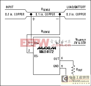
Figure 10. This high-side current monitor (MAX4172) employs a PC-board trace for RSENSE.High-Side-Monitor Applications
The circuit in Figure 11 is a variable linear current source. IC1 converts R1 current to a proportional output voltage, enabling the voltage regulator (IC2) to produce a regulated output current. To set a specific, regulated IOUT level between 0mA and 500mA, apply 5V to 0V at ICONTROL (5V sets IOUT = 0mA, and 0V sets IOUT = 500mA). As an alternative, you can introduce a D/A converter as shown to provide digital control of IOUT. For 12-bit resolution (60μA per LSB), the DAC can be a parallel-input MAX530 or serial-input MAX531. For 10-bit resolution (250μA per LSB), the DAC can be a parallel-input MAX503 or a serial-input MAX504.
Figure 11. A variable, linear current source (MAX4173).
The Figure 12 circuit is a 0-5A programmable variable current source. Generating 0A to 5A with a compliance range of 4V to 28V, it offers two advantages: The 12-bit D/A converter (IC2) makes it digitally programmable, and the switch-mode step-down regulator (IC1) makes it more efficient than the alternative current source with the linear pass transistor. Applications include battery charging and DC motor control.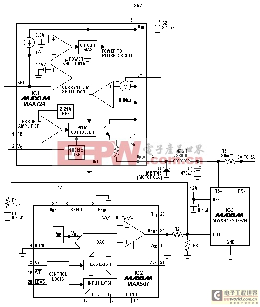
Figure 12. A 0-5A programmable current source (MAX4173).
Widespread use of the universal serial bus (USB) has led to a variety of overcurrent protection circuits for supply rails in the range +2.7V to +5.5V, but few products are available for voltages above that range. The circuit breaker in Figure 13 operates on supply voltages to +26V and trips at a programmed current threshold.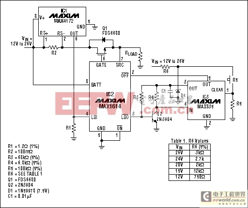
Figure 13. This high-voltage circuit breaker (MAX4172) protects to 26V.
模拟电源 电源管理 模拟器件 模拟电子 模拟 模拟电路 模拟芯片 德州仪器 放大器 ADI 相关文章:
- 采用数字电源还是模拟电源?(01-17)
- 模拟电源管理与数字电源管理(02-05)
- 数字电源正在超越模拟电源(03-19)
- 数字电源PK模拟电源(04-03)
- TI工程师现身说法:采用数字电源还是模拟电源?(10-10)
- 开关电源与模拟电源的分别(05-08)