multistage wilkinson splitter
I'm now designing a 5 stages 'cascade' Wilkinson power divider (bandwidth 0.5GHz -6.5 GHz) on RF-60A (Er=6.15, H=1.542mm)according to "A general design formula of multi-section power divider based on singly terminated filter design theory".
With the value I calculated according to the specifications in my case, I can have exactly the same perfect performance in ADS schematic simulation as in the paper. (The isolation resistors I used to simulate is the KOA 0603 model from modelithics) However, when I generate the layout and simulate in Momentum, the isolation(S32) goes very bad from -20dB to now only around -7dB while the insertion loss and return loss still keep the same.
I've been stucked here for quite long time. Anybody, pls help me
BR
kevin
Any capacitance across the isolation resistors will hurt your isolation. Simulate your splitter with ideal resistors and a parallel capacitance on each resistor of, say, 100 to 200 fF and see what the isolation does. This might be your problem.
If so, find some resistors that do not have wrap around terminations.
Hi biff44
Thanks for your reply.
You saved me! When I connected a parallel capacitance of 100-200fF, S32 is still very good. But when I increased it to 300-400 pF, then it is exactly the same as the result I got in the momentum. I didnot notice this problem though I've thought of it because I choose the model 0(Sim_mode : 0 for full model, 1 to ignore parasitics) when doing simulation in the schematic.
I've been wasting so much time on modifying my topology... Now my next work is to find suitable resistors, lol
I've prototyped a 12GHz Wilkinson on a Ultralam2000 laminate and got very bad results. Biff, what resistors do you recommend? Ordinary 100Ohm 0603 is unusable...
I use 0603 resistor for 10GHz power divider, the result seems ok(S32 -25db)
Same question....
And is it possible to simulate the circuit in momentum before prototype? Where can I find the suitable model?
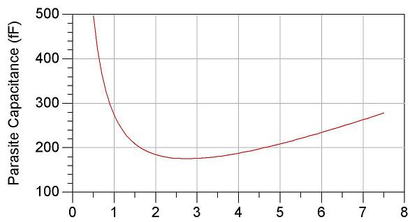
Sorry me for the mistake.@@ Here is the simulation result for the 350Ohms KOA 0603 RK73B1
Something like these "partial wrap" resistors:
http://www.globalspec.com/FeaturedPr...ations/34964/1
BTW, I assume that was a type and you meant fF, not pF in your simulation.
Added after 4 minutes:
ALso, you CAN compensate the design somewhat to allow for some resistor capacitance. But you need an accurate model of the resistor before optimizing. The capacitance across the resistor imparts a phase shift, so the 180 degree/0 degree vector cancellation of the wilkensen sections are miscentered by the parasitic capacitance.
Thanks Biff! Additionally what is the optimal transition from microstrip to semi-rigid coax cable at 10+GHz? Is UT-085 semi-rigid small enough?
Could you please tell me which resistor u use? Did you simulate it before manufacturing?
multistage wilkinson splitter 相关文章:
- MultiStage FrontEnd Receiver Desing Using BF998
- designing multistage (multisection) wilkinson power divider
- Formula for calculating multistage wilkinson power divider
- multistage wilkinsons
- How to design unequal Wilkinson divider according Taylor amplitude distribution coef.
- Resistors in N-Way Wilkinson Power Combiner