[Help] Improvement on LNA design
I'm trying to a LNA (untuned common emitter amplifier) for my FM receiver to amplify the RF signal from the antenna before sending it into the oscillator.
Although the signal is being amplified, but it's no longer a perfect sine wave (when i input a sine voltage). Here's the simulation i obtained from ADS. I was hoping someone could advice me on this matter.
Thanks in advance.

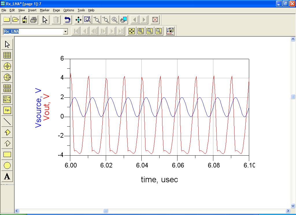
Linearity issue, my friend.
If you do not degenerate the bjt you'll have signal compression for very low input amplitudes.
Try to simulate with 1mV at SRC2 amplitude and you'll see the difference.
I hope it can help.
Mazz
Hi mazz,
yes, you are right, thanks.
"If you do not degenerate the bjt you'll have signal compression for very low input amplitudes. "
You mentioned the above sentence. Can you elaborate more about it?
Another question, so the voltage range of the input signal can only be in mV range?
Is there any way i can correct this problem (change in schematics?) instead of changing the input voltage, because i've already build an FM transmitter that transmit the signal around 3 volts.
Thanks
the transmitter will transmit the 3 volt to an antenna , th LNA will pick the signal from the receiver antenna
usually the LNA input signal is very weak , even less in micro volt range
khouly
oasis4355
I agree with khouly.
just one question:
do you have idea of "noise figure", "impedance matching" and "small signal gain" concepts?
Thanks.
Mazz
Hi,
Sorry, no idea. Still in my first year, dealing with Maxwell's...
Couldn't you kindly explain briefly to me?
Thanks
usually , the RF is measure in power terms , , so the LNA will pick the power from th antenna , and hence , amplify it
the LNA , should have good power gain , and also have a very low noise figure
noise figure of the antenna is a measure how the LNA itself increase the noise in the received signal
u should read , some RF books , u can check RF microelectronics of Behzad Razavi
Khouly
I agree with khouly once again.
Explain these concepts in brief messages is difficult.
I strongly suggest to you the Razavi.
Mazz
I agree with both. Designing a LNA involves lots of trade off e.g Gain Vs nf, IP3, 1-dB CP,,,try to read some journals (IEEE), and YES Razavi book will help a lot.
also u can check the book by Clavin Pelet
Radio Frequency Integrated Circuit Design
khouly
why u don't put a inductor on the collector
if u want the LNA is tuned , u should make the inductor in the collecter as load ,or it could be a part of output matching network
Khouly
Do you mean 1nF for C1 ?
i mean the inductor can act as an AC choker,or the AC signal can run to the collector
Thank Khouly,
I read the book by Behzad Razavi to have a more understanding about LNA and noise figure. But in this case, what's the degree of the noise figure? And how can i prove it through ADS simulation? Please advice...
Thanks in advance.
in ads u can simulate the noise figure using the s paramter simulation , and u need the model if the transistor , and begin the noise matching and so on
khouly
oasis
to let you understand the required effort to have good results, let me say that all the needed knowledge is in a couple of universitiy sessions.
If you think you can do it in a couple of days, let me suggest to "retune" your target.
Unless you are a genius, of course ;)
Mazz
Hi...
Thanks for the info, it really helps.
Actually i'm on holidays, just to do a couple of things to fill in the time.
oasis4355
Which software r u using for simulation?
Hi,
I'm using Advance Design System 2004A.
Improvement LNA design 相关文章:
- s Parameters of LNA Improvement
- Improvement of gain and directivity of a patch antenna
- Improvement of Linearity in Differential Amplifier at 35Ghz
- improvement in antenna performance for wban (wireless body area network)
- Radiation Efficiency improvement for miniaturized slot antenna
- bandwidth improvement of antenna