4 way wilkinson
I've already finished designing a 2-way wilkinson power divider from 0.8 to 6.45GHz in microstripe technology. But I met problems when I am trying to cascade another two at each output ports with 50 ohms line to form a 4-way PD. The simulation results in Momentum and Microstripes are far from what I expected.
Could anybody share me some valuable experience? Some good references on this topic are also welcomed. :D Thanks in advance.
kevin
it is the same as 2 ports power devider that satisfies the match and power deviding
The only reason you would have problems is if the port return losses for your design were poor. What were the return losses?
Hello Kevin,
Upload your ADS momentum or DXF files with substrate details so that it is easy to help or comment ...
---manju---
Thx guys,
It seems the return loss, especially at the frequency above 6 GHz, is introduced by the bents of 50 ohms line. There's no problem if I directly cascade the PDs together.
The subsrate I am using is Er=6.15, H=1.542, T=35um, tanD=0.0018. Is there any way to improve it?
BR,
kevin
hi,
maybe I'm wrong, but a wilkinson requires 70ohms lines which are lambda/4 in length to work properly. In the frequency bandwidth that you indicate (6GHz more or less), the deviation from the theoretical lengths will be very large, affecting the device behaviour.
I see that you simulate with momentum. probably you are also affected by some line-to-line coupling. some drawing of the circuit could be of help to analyse the problem.
regards
For 2 port wilkinson needs using 70.7 Ohm line quarter wave trafo for transform between 100 input to 50 Ohm output (each leg, 100//100 Ohm give 50 Ohm on input) - and for wideband i think you must using some kind of multi section or tapered shape of quarter wave line. Shunt resistor between output port shall be 100 Ohm
for 4-port wilkinson you must make 200 Ohm - to 50 Ohm quarter wave trafo - 100 Ohm line quarterwave (each leg), and for wideband, same here, you possibly need some multi section or tapered shape of quarterwave line. Shunt resistor between output is a output impedance (50 Ohm) coupled in star together
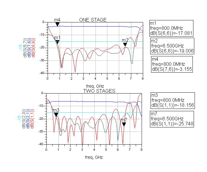
Single stage quarter wave line in 2-port wilkinson have only around 1/3 octave bandwidth if you want return loss and isolation better than 20 dB on all ports.
single stage quarter wave line in 4-port wilkinson have 20 dB return loss limit on common input only to 1/6 octave, but return loss and isolation on output is now >= 1/2 octave
(bigger step quarter wave transform make bigger Q-value and smaller bandwidth)
If use 3 * 2-port single stage quarter wave line wilkinson to make 4-port give better bandwidth, worst is isolation between out port have 1/3 octave for 20 dB isolation limit.
Ok, lets take this a step at a time.
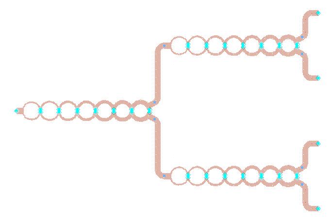
If you cascade the 3 two-way splitters directly together they work well. If you then space out the splitters with 50 ohm lines with bends in them, they do not work well.
The conclusion is that the bends in your lines, or the width of the strip, or something else, is causing the two 50 ohm lines to not look like 50 ohms. So, use an analysis program to simulate the bends, and and microstrip line, and adjust the parameters until they are a good 50 ohm match to well above your operating frequency. For instance, you might have to chamfer the bends if they are right angle ones. You might want to make more gradual circular bends if you have the room.
Thx Biff44,
I have attached the layout and the simulation of the 50-ohm line used as the connection of two power splitter. Finally I understand the the return losses come from the bents of both the inter-connection and the output ports.
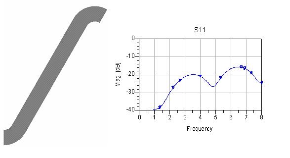
Yes, I have tried to tune the length and width of 50 ohms line. However, it seems only the performance within 6Ghz has been changed meanwhile the return loss above 6GHz just slightly changed. To use an more smooth bent works better but will increase my size a lot. Now with the bents I show in the attachments. I got dimension of final layout around 119mm, which is quite close to the requirements(125mm with box) in the spcification.
Added after 9 minutes:
Also thank you very much xxargs,
Maybe I should consider to build a one-stage 4-way 'folk' power divider, which may avoid the annoying right angle bents.
Could you pls tell me more about how to design a multi-section n-way symmetric PD? I suppose it is the same as a 2-way PD (only 200 ohms instead of 100 ohms for the quarter wave transformer.) If so, then it will be impossible to relize a 157-ohm quarterwave length strip (W=0.04mm) for the first section in my case.
BR,
kevin
For 2 port wilkinson needs using 70.7 Ohm line quarter wave trafo for transform between 100 input to 50 Ohm output (each leg, 100//100 Ohm give 50 Ohm on input) - and for wideband i think you must using some kind of multi section or tapered shape of quarter wave line. Shunt resistor between output port shall be 100 Ohm
for 4-port wilkinson you must make 200 Ohm - to 50 Ohm quarter wave trafo - 100 Ohm line quarterwave (each leg), and for wideband, same here, you possibly need some multi section or tapered shape of quarterwave line. Shunt resistor between output is a output impedance (50 Ohm) coupled in star together
Single stage quarter wave line in 2-port wilkinson have only around 1/3 octave bandwidth if you want return loss and isolation better than 20 dB on all ports.
single stage quarter wave line in 4-port wilkinson have 20 dB return loss limit on common input only to 1/6 octave, but return loss and isolation on output is now >= 1/2 octave
(bigger step quarter wave transform make bigger Q-value and smaller bandwidth)
If use 3 * 2-port single stage quarter wave line wilkinson to make 4-port give better bandwidth, worst is isolation between out port have 1/3 octave for 20 dB isolation limit.