questions about the transient response of a pll
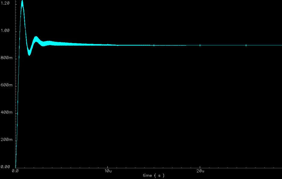
i am a freshman in pll design.i have designed a pll in transistor level.the model corresponding to the first waveform is implemented with veriloga presented as a comparision,and the simulation time is 30u.the circuit corresponding to the second waveform is implemented with transistors,and the simulation time is 3u.according to the waveform,we can see that the curve is not a line,but at some instant the curve has different values.it is more obvious in the third figure,which is a part of the second figure zoomed out.what cause this?
additionally,the control voltage is not stable for a long time.i have simulated the circuit with the simulation time of 50u.the amplitude of the voltage indeed decreases,but slowly and still not stable.instead,the veriloga model becomes stable quickly.the veriloga model and the transistor circuit basiclly have the same parameters,and what is the reason?
give me some explanation and advice,please.thanks a lot.i am sorry that i can not upload the image bigger
best regards
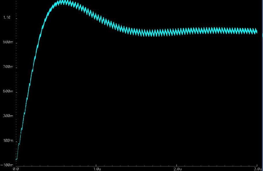
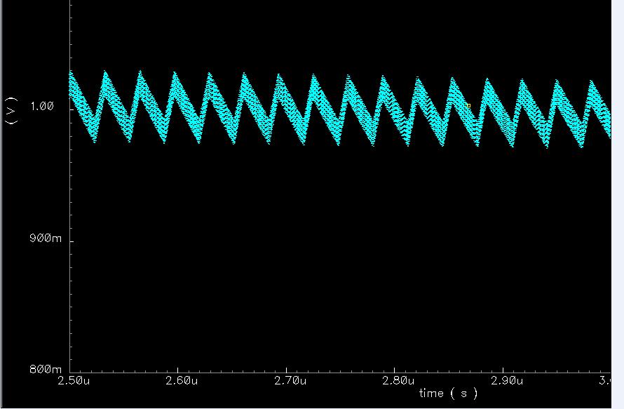
Concerning the ripples at the response, we once faced the same problem and it was a simulator's inaccuracy at calculations because the time step was not small enough .
Concerning, stability, the PLL loop is at least a second order feedback system and thus its response depends on the phase margin .If PM is smaller than 60 degrees, ringing will be seen at the response that would decay .You should simulate for longer time to ensure that the riniging settles for negligible amplitude .The behavioral model would settle before the actual circuit because the used model is most probably a linear one,thus converges faster and gives results close to theory while the actual circuit takes in considerations non-linearities like that of the VCO's gain which would need longer time to settle .
I do not understand. Are the pictures shots of an oscilloscope testing a real physical circuit, and they are not agreeing with your previous simulation, OR are the pictures just shots of the simulation?
- Different Results in Transient Simulation with S-parameters from file in ADS
- Transient Concerns in Wireless Power Transfer
- S-parameter vs. Transient simulation in ADS
- ADS difference between SP simulation and Transient simulation
- ADS transient simulation with snp blocks
- CST Transient, Frequency and Integral Solver Different Results