fft oth harmonic
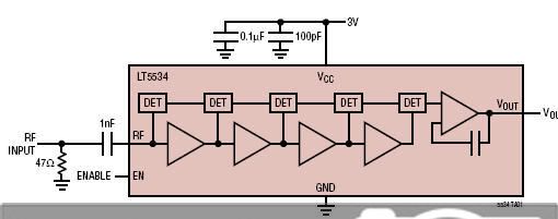
I am working on LogAmp detector development using ADS tool.
Used topology:
There are the uncompromises among Transient (Trans), Harmonic Balance (HB) and Envelope (ENV) simulations
when I try to observe output time domain response as following plots:
The uncompromising points are:
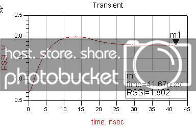
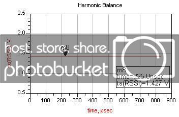
1. Trans simulation introduces very different output steady level (compare with ENV and HB)
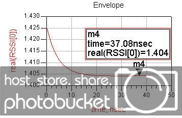
2. Trans and ENV simulation show opposite equilibrium-reaching process
Could anyone give me comment on the differences?
Thanks alot for help
u need to check the , over sampling in both HB and ENV
the ENV used when the envelop is changing , if u use the constant envelop, Transient and HB shuold be the very close
also u need to check the different solver options in HB and ENV like krylov solver and it is options
can u send the porject , so we can check it
khouly
Hi khouly,
Thanks for your response!
Yes, I have tried HB and ENV simulations for different harmonic order, FFT oversamples, Convergence modes, direct and Krylov solvers - almost same responses at the output
In my case, with same circuit, same signal source P_1Tone at same RFpower and RFfreq, HB and ENV introduce very close results meanwhile Transient doesn't ---- that's the confused uncompromise.
Sorry, I am not allowed to release project's details
hi abs1211
r u sure that in transient the singnal is the same as the ENV or HB , special in tran u use a time domain source
khouly
Hi khouly,
From an HP material, following is what I got:
Transient simulation:
Analysis performed in the Time Domain
Use any Source
Solutions use Newton_Raphson iterations
You get Amplitude vs. Time
Time Domain data can be transformed: FS
So, I used same signal source for transient simulation as I used in HB and ENV.
From investigation, I realised that there is a bit different at the summed point, right before the output opamp and as the result a significant different at the output.
I still keep investigating the root of the problem and any of your suggestion is highly appreciated.
Regards
in transient simulation , did u add a source resistance , coz the sources in the time domain don't have internal resistance , and the freq domian sources used in HB have internal 50 ohm impedance
take care of this issue
khouly
Thanks for your suggestion.
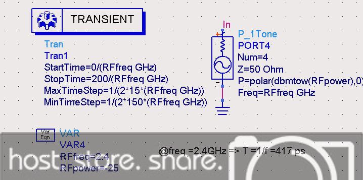
These are the settings I used for Transient Simulations
1. P_1Tone as signal source
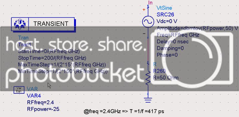
2. Vtsin as signal source
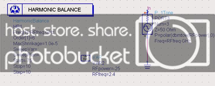
and these are the settings for HB Simulations
Two settings used for transient simulations result similar outputs that are uncompromised with HB simulation output as I showed in the first post.
Hope to hear more from you!
did u check the option in the transenit solver of convelution analysis
check this photo
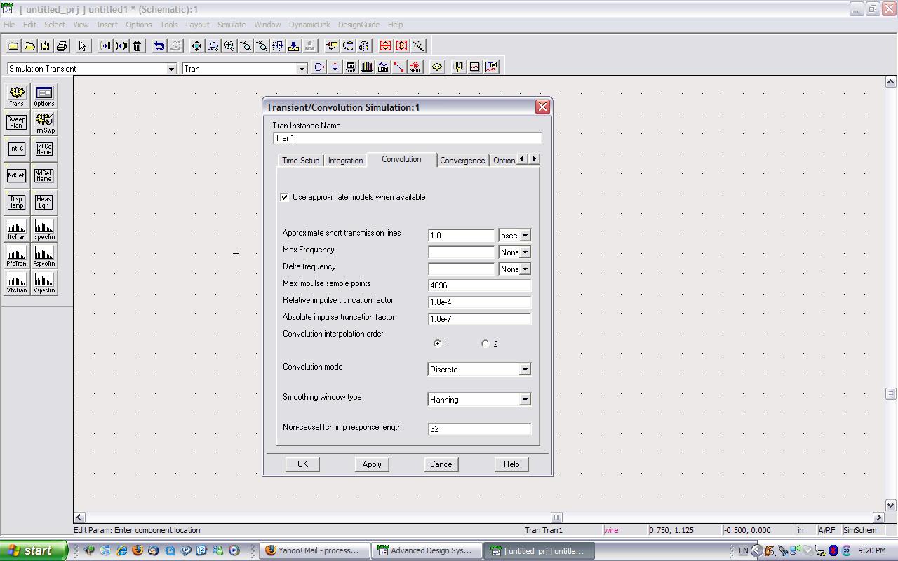
use this option
khouly
I guess, initialization of the simulations are different.
For this circuit, the best way to observe the output signal is to make a transient analysis because this is a RSSI circuit. Output level will vary with signal amplitude.
The settling behaviour what you see in transient simulation when you apply a signal level at the input..( If I'm wrong, please correct me..)
Than you should look t 0th harmonic after FFT..( what is DC component of the output spectrum)
@khouly: I did check the option in the transenit solver of convoution analysis as your suggestion - no difference for the HB output response
@BigBoss: There is no initialization for the simulations I run. Could you be more clear? and I don't really get your ideas about 0th harmonic after FFT?
i have an idea , in ADS there is something called transinet assisted Harmonic balance , try to see this option , and try it , this may lea u to something good
khouly
Eventough you don't assign an initialization state, every simulator puts one to get its own start-up conditions.Therefore HB or transient analysis "might be" used different initilization condition.So, simulation results seem to be different due to this difference..
In FFT, Oth harmonic is considered as DC component, so if your circuit gives you a response acccordingly with your input level, basicly you can check your circuit by changing input level of your circuit while observing output DC level.To do this, connect a VAC signal source at the input and change its level ( parametric simulation ) and observe DC component at the output of your circuit.It will give you typical RSSI response..
ENV is a better choice to calculate transient response because it's faster than transient simulation.
if u want to optimize your circuit,HB is a better chioce,HB can calculate circuit's stationary response. i have designed a CMOS detector to detector to demodulate RFID input signal. it works well when input signal is about -4 dbm.in my work ,I use HB to optimize my circui,then i use Transient to simulate the speed of demodulation. in my view ,to simulate and optimize LogAmp detector,HB is the best choise.
all what you should do is to find the voltage of Vout[0],not Vout[1].
hi,
asb1211, when you perform transient simulation with Rsource added to Vtsine (2. Vtsin as signal source) I think the 50 ohm Rsource must be set after the signal source Vtsine, in order to compare with HB simulation for example.