Positive and negative reactance in dipole antenna
reactance -+ cause increase on VSWR, and disrupts pattern and gain. Also reflection (cos of impedance mismatch) occurs. reactance actually cause phase shifting beetwen voltage and current.
And first Question: half vawelengt dipole (size is always %2-%5 smaller cos of parasitic effect) has a real impedance(no reactance) if you reduce or increase size out of half dipole size reactance + or - occurs.
Despite the resistive match between antenna and transmitter/receiver a reactive match is also required (with opposite sign). Non-zero reactance increases SWR of the antenna. Positive value of reactance means that antenna is too long (electrically, it's a simplification, but rather good), such an antenna acts as inductance (with radiation resistance in series). On the other hand, a negative reactance means that antenna is too short, and acts as capacitance (with resistance in series again).
The performance impact of reactive component of impedance is higher SWR when antenna is not matched. However, if it results from unmatched antenna dimensions, it will result in degraded radiation pattern.
thanks for the answers but dear shg could you plz cheack your answerto make sure coz u have written that Positive value of reactance means is too long and a gain you have writtern positive reactance means that antenna is too short so could u plz correct it for me again thanks for answers
Thanks for pointing this out.
Negative reactance means capacitive of course.
can i ask how does it effect i mean what is the advantages or disadvantage of been capsitive or inductive ?
At the input side, reactance should be ideally 0 to achieve a good SWR.
The current distribution of the antenna can be change be top-loading. This changes the effect length and thus the radiation pattern.
i have designed yagi uda antenna considering a channel works on frequcey 199.25 mhz chanel 11 in north cyprus... using 4nec2x and get these results number of elements 5 and the gain is 9.7 and input impedance was 44.5-j32.03 and effecency was 96.88% so according to theoritical part i think i got good results coz gain is high resistance is good to match 50 ohm and effecncy have high percentage so what do u think dear friends of my results and how does this negative value effects on my design
It seems you have a mismatch at 199.25 MHz. 44.5-j32.03 ohms gives a return loss of 9.7 dB = VSWR 2.0.
Is your Yagi antenna design really resonant and optimized for 199.25 MHz? How does the input impedance vary over the frequency range from 150 to 250 MHz? How about the gain over this freq range?
You have to improve the matching of the radiator/dipole element. How do you feed the radiator of the Yagi? Zipping and posting your 4nec2x design files would help.
I believe 9.7dB is S21 and not S11.
If my calculs are OK, with an impedance of 44.4-j32.3 (assuming 50 ohm system)
S11 = ((44.5-j*32.3 - 50)/(44.5-j*32.3 + 50)) = 0.328 /__-80.8o
this means -9.68 dB of return loss.
Transfered power ratio to load 1-|S11|^2 = 0.892 --> 89.2 %
So expect efficiency less than 89.2 %
dear friends its nice to see ur answers but im not that good in these calculations and i dont have that much good back ground ....i just want to know is it good answer or bad (can it be used in practical life ) and what about nagetative value how does it efect...... im sending my work
Well,
first lets talk about efficiency. In your case "Radiated efficiency" is around 96.88% this means that of the tranfered power to an antenna (antenna viewed as a load) the 96.88% is radiated, and 3.12% is loss (ohmic loss etc).
But this NOT mean that 96.88% of the power delivered by the source is radiated, why? because your source impedance is a 50 Ohm system and is mismatched to antenna, so some of the power is reflected and not 'absorved' by antenna. In your case 89.2% is transfered, so including antenna loss, you have a global radiation efficiency of 86.42 %.
If you match the impedances you'll have better system in this sense. (And the power transistor of your system will be happy).
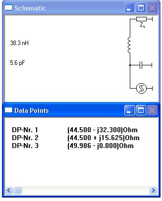
Here I give you one example of one matching circuit of your antenna to 50Ohm system, the component values are close to commercial values, for C = 5.6 pF and L = 39nH also can be practical.
thanks but so u mean i have aproblem just in matching the impedance ....how could u find these valuses ....does the negative value effect on the performance of antenna
could you plz explain me how did u get this value
With smith chart u can calculate.
refer shareware..
reactance Positive antenna 相关文章:
- FM BJT Reactance Modulator (Proof on Oscilscope)
- How to extract the Resistance and Reactance of a Inductor in Cadence Software?
- Antenna Resistivity and Reactance Help
- reflection and corresponding reactance
- Relationship between Reactance and phase distribution of an antenna element
- something about the pure reactance, need help