Looking for schematic of an envelope detector circuit
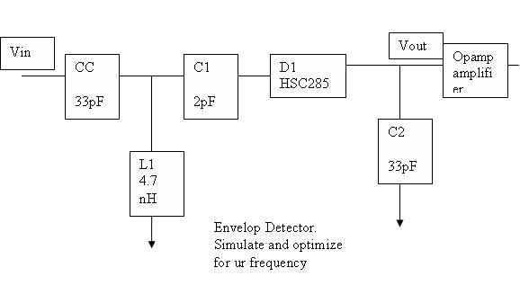
I am looking for a simplest envelope detector circuit which consists of one diode,and a low pass (RC) filter.the envelope detector circuitry should be able to extract the 900MHz modulated signal.
If anyone has the schematic(with the RC value)/simulation(Agilent ADS) on the above mentioned specs,hope you could help me here as I need it urgently.
THANKS VERY MUCH!
Have a nice day.
No one knows anything bout it?
See attached
Hi,
this subject interests me
Do you know what kind of OPA is able to not disturbing the detected signal due to its input impedance ?
I think it's critical .
That circuit does not look right to me. There is no path for DC thru the diode. As a start, I would eliminate C1, and replace C2 with a 270 ohm resistor (a good balance between sensitivity and detection speed). I would also increase the L1 value so that it had at least J200 ohms at 900 MHz.
after simulating at 900 Mhz (transient) :
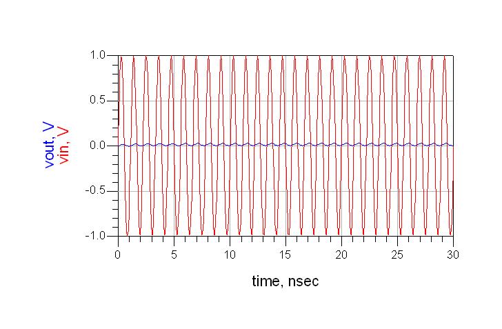
[/img]
Hi,
The circuit is not consisting of discharge path, so it can not work with the dynamic signals.
THis circuit must be able to follow the RF input signal envelope, how to check its capability?
could you help me in this way?
No one knows anything about it?
A diode detector can have maybe 25 dB or so of dynamic range. You want an RF Power source that can be pulse amplitude modulated. In the high power state, you want an RF signal close to the maximum signal range to be detected. In the low power (off) state you need to attenuate that maximum RF power state by at least that 25 dB, although more attenuation is ok too.
A standard microwave switch with pin diodes or fets is fine to do the pulse modulation. If you application is slow, a lot of times the RF signal generator can also be amplitude modulated to produce this RF pulse.
It is important to use an analog load that is the similar in impedance to one you will use in the final circuit. For instance, if you are using an op amp inverter for the detected video voltage, you would do the test with a high impedance oscilloscope input. This is important if you want to get an accurate view of the detector's response time.
Hi all nice topics and really intresting..... i designed FM detector using envelop detector for 315Mhz carrier frequency but i have a problem for calculating RC values to get smooth audio signal ...GVVIN you simulate the reciever for 900Mhz can u help me how to get the values for 315Mhz and thnx in advance
I made detector for 500MHz using this application note. It works great.