attenuator question..
In Attenuator circuit ,
1. why we need connect ground pin to capactor to ground ?
2. why we apply capacitor across MOS gate-drain ?
Thanks.
I don?t think there is an external capacitor in a CMOS attenuator. Probably in the schematic is mentioned the internal CMOS capacitors.
Usually a shunt resistor is used (across the series CMOS) to forces the transistor to turn off at high attenuation.
May I ask to share the complete schematic circuit?
This helps us in understanding the problem
attach ckt
the schematic could be wrong while editing.
This is not the recomended circuit for attenuator action.
Verify the same at http://www.macom.com/DataSheets/MAADSS0008_V1.pdf.
this schematic is agency provide ,
i don't know what's wrong ?
Thanks.
May I know the frequency of operation?
From where these control voltages are generated?
Input is 45Mhz signal.
control voltage is 0/vdd or vdd/0 to control attenuation.
but I still don't know cap real meaning .
thanks.
Sounds interesting application as 45MHz signal needs controlled attenuation.
I have few more questions to you.
Is this 45 MHz is un-modulated one?
Is it clock distribution network?
Why the design needs controlled attenuation at 45MHz frequency?
May I know the input and output sections of this attenuator block.
I mean what is the circuit that is driving this attenuator and the attenuator output is going to which section?
Some times the driving and the to be driven stages lead in to such design modifications not practiced by the vendor.
I think the datasheet is confusing: It contains the following image.
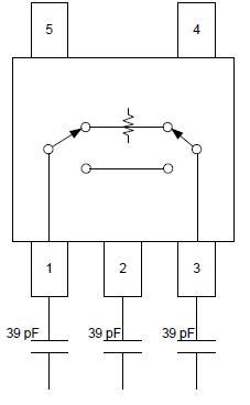
Never mind it, pin 2 is the GND node so connect it to gnd. It is no RF I/O.