iip3 of the attenuator from cadence
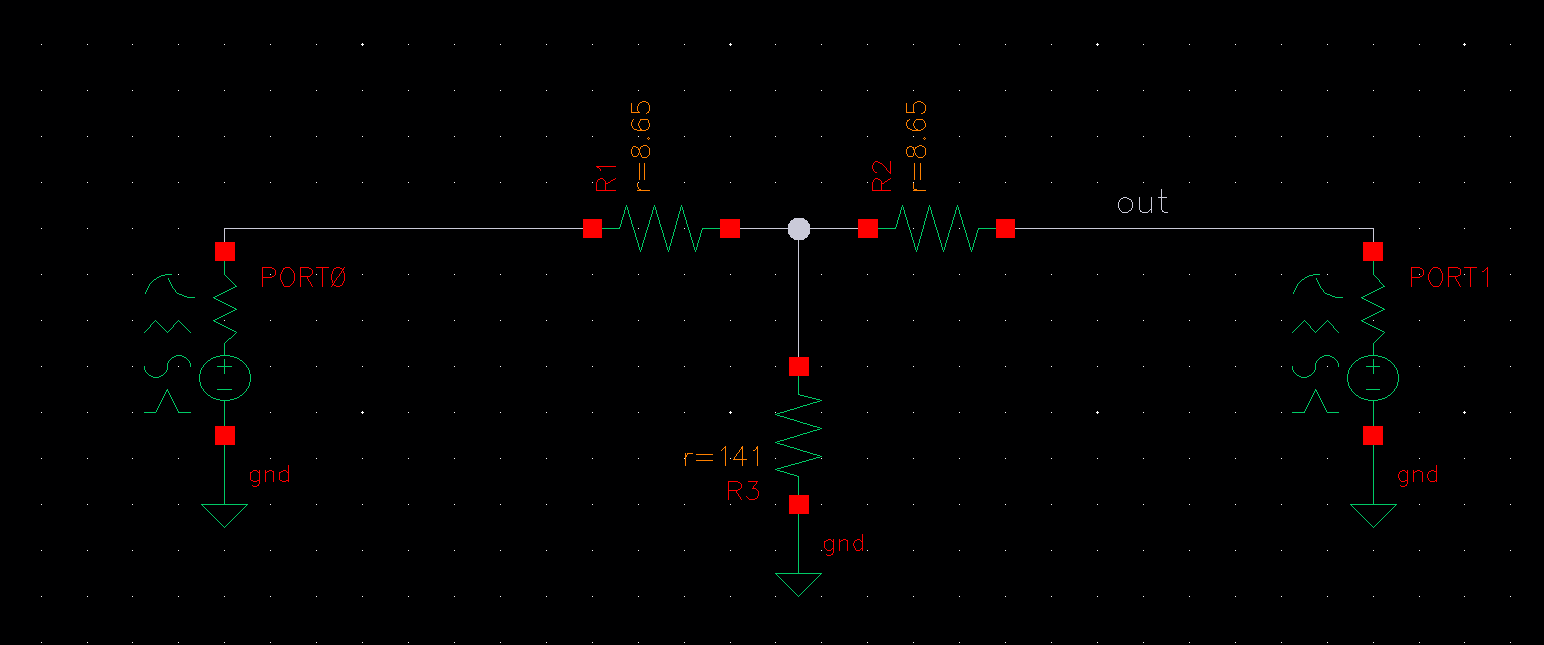
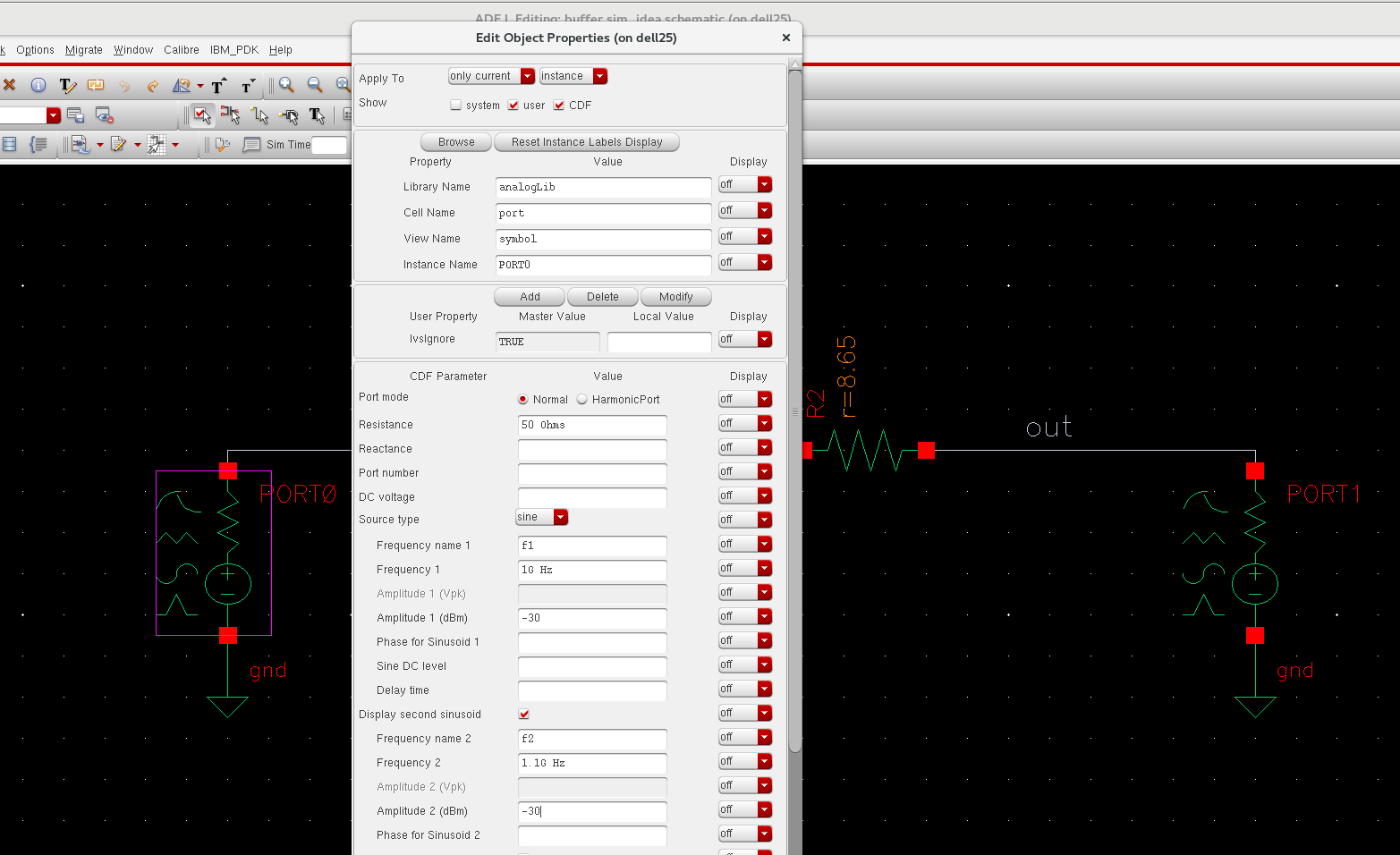
The two input signal are f1=1GHz and f2=1.1GHz respectively, and the input power is -30dBm for both input signal.
Run QPSS, the result is that:
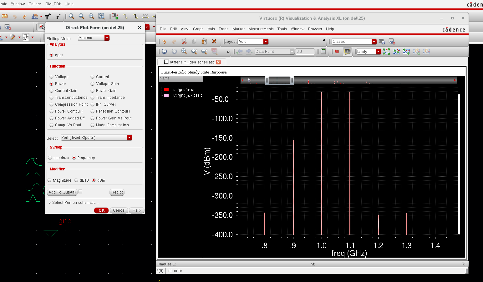
At 1G and 1.1G, the spectre are both -33dBm, that' correct. (Input is -30dBm, and attenuation is 3dBm, so it is -33dBm.)
For the modulation signal: 2*f1-f2=0.9G, and 2*f2-f1=1.2G, why the amplitudes of the two modulated signals are quite different? Thanks.
Attenuator is linear perfectly.
So there is no distortion.
0.9GHz : -150dBm
1.2GHz : -350dBm
These are almost zero.
So they are same value.
What analysis engine do you use as QPSS, Shooting-Newton or HB ?
I think you use Shooting-Newton-QPSS.
Dynamic range of spectrum from shooting-newton based analysis is far less than 80~90dB.
And treatments of f1 and f2 are different in Shooting-Newton-QPSS.
f1 is a large signal.
f2 is a moderate signal.
Your analysis should show a perfectly linear attenuator. I believe your problem lies with the size of the steps that the analysis engine uses - it is probably too coarse to give you equal sidebands. You might want to see if you can change the step size (but it will cost you time).
What do you mean by "the size of the steps" ?
Yes, I used newton before.
Now I changed to HB , and it works. The two modulated signals' amplitude are the almost the same now. Thanks.
The "size" option means conservative, moderate and liberal from qpss setting. Thanks.
It can never be.
If dare to say, it is overs ample factor or order of tone.